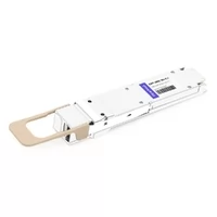
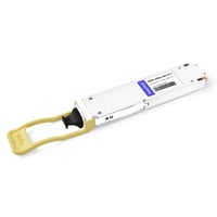
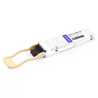
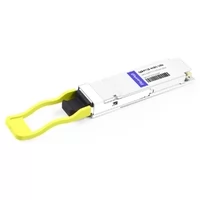
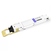
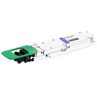
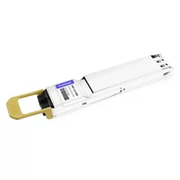
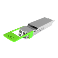
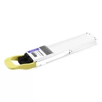
The installation of 800G OSFP modules without adequate thermal management leads to equipment overheating, network connections dropping, and decreased equipment operational time. The actual power usage of devices exceeds their specified power requirements by 15-25%, which creates obstacles for deployment teams to handle. The 32-port 800G switch causes a heat output that exceeds 1,000 watts because its optical modules produce almost 50% of that thermal energy.
The ability to manage thermal conditions determines the success of network operations. Using OSFP modules at temperatures higher than their specified limits results in two negative effects because it raises the bit error rate and activates protective throttling mechanisms while decreasing the system’s average operational time. Data center teams frequently miscalculate their cooling needs because they focus on switch expenses instead of understanding the thermal systems required for operational support.
The guide delivers an all-inclusive thermal management system for OSFP applications. The thermal design differences between IHS and RHS variants and actual power consumption values, rack cooling methods, and thermal budget calculators will be taught to you. This guide provides everything needed to manage 800G switches and handle 1.6T migration while selecting modules and solving thermal problems.
For comprehensive OSFP deployment guidance, see our OSFP data center deployment guide.
Understanding OSFP Thermal Design
Why OSFP Thermal Management Matters
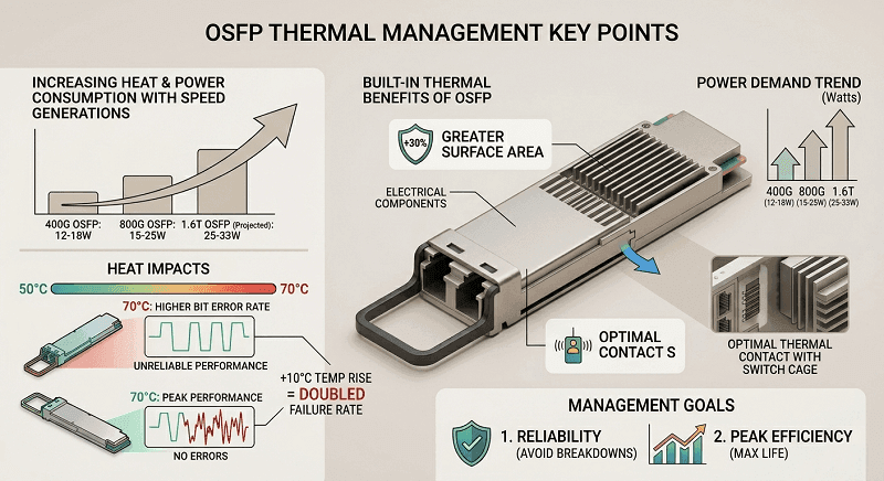
OSFP modules generate significant heat due to high-speed DSPs, laser drivers, and electrical components. Power consumption has increased with each speed generation:
- 400G OSFP: 12-18W per module
- 800G OSFP: 15-25W per module
- 1.6T OSFP: 25-33W per module (projected)
The thermal load between two points in the system causes network performance impacts that can be observed. The failure rate of electronic components increases by approximately double when the operating temperature rises by 10°C. Bit error rates increase for modules operating at 70°C compared to modules that run at 50°C. Equipment thermal management requires two functions, which include protecting equipment from breakdowns and achieving peak efficiency throughout its operational lifespan.
The OSFP form factor provides built-in thermal benefits. The OSFP modules, which have 30% greater surface area than QSFP-DD, achieve better heat dissipation performance. The system’s design enables heat sinks to be installed while establishing optimal thermal contact with switch cages. The design choice of OSFP power handling capacity increases with speed improvements.
OSFP-IHS (Integrated Heat Sink)
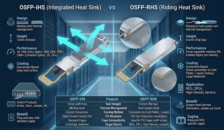
The OSFP-IHS modules feature thermal management systems that operate without external assistance in air-cooled systems. The IHS designation stands for Integrated Heat Sink, indicating the module includes its own heat dissipation mechanism rather than relying entirely on the host system.
Design Characteristics
IHS modules measure 13mm in height, including the integrated heat sink structure. The thermal design uses one of three configurations:
- Open finned-top: Exposed metal fins maximize surface area for convective cooling. Air flows directly across the fins, carrying heat away from the module. This design provides the best thermal performance for air-cooled environments.
- Closed finned-top: Partially enclosed fins balance cooling performance with mechanical protection and electromagnetic interference shielding. The enclosure prevents physical damage to delicate fins while maintaining adequate airflow.
- Flat-top: A simple metal casing without external fins relies on chassis airflow and conduction through the module base. Suitable for moderate power applications in well-designed cooling environments.
Thermal Performance
The IHS modules manage a power range between 16 watts and 18 watts when they use standard grey optics, which include SR8, DR8, and FR8. The extended-power versions of the system enable users to operate coherent optics ZR and ZR plus at power levels exceeding 20 watts because they provide additional thermal capacity. The IHS modules use their self-contained design to work with standard OSFP cages, which exist in Arista, Cisco, Juniper, and other major switch vendor products.
The system uses forced convection as its cooling mechanism because switch fans create airflow that moves through the chassis and across module heat sinks and finally exits through the exhaust. Thermal efficiency depends on airflow velocity, intake air temperature, and the thermal resistance of the heat sink design.
OSFP-RHS (Riding Heat Sink)
OSFP-RHS modules take a different approach to thermal management. The RHS designation stands for Riding Heat Sink, which describes the module’s design that operates on its own thermal management system because it connects with the host system’s heat dissipation system.
Design Characteristics
RHS modules feature a flat metal top surface that reaches a height of 9.5mm, which is lower than IHS variants. The flat surface makes contact with a thermal interface material (TIM), which transfers heat to the cooling solution that the host system provides. The design eliminates the integrated heat sink, relying instead on system-level thermal management.
RHS modules require specific cages designed for this thermal interface. The cages include different positive stops to prevent accidental insertion of RHS modules into standard IHS cages, which would result in inadequate cooling and potential thermal damage.
Thermal Performance
The design of the RHS system provides improved heat transfer performance to its advanced cooling systems. The RHS modules achieve power handling capabilities that match IHS variants through their direct connection to cold plates and centralized heat sinks. The system-level approach of the system distributes thermal load across multiple surface areas, while it allows for liquid cooling systems to be integrated.
RHS modules are particularly common in network interface cards (NICs) and data processing units (DPUs) because space limitations and shared thermal systems make it impossible to use integrated heat sinks. The design of the system includes a flat profile, which enables certain configurations to achieve greater port density.
IHS vs RHS Thermal Comparison
| Feature | OSFP-IHS | OSFP-RHS |
| Height | 13mm | 9.5mm |
| Cooling Method | Module-level air cooling | System-level conductive cooling |
| Primary Medium | Forced air convection | Liquid cold plates or centralized heat sinks |
| Max Power | 20W+ | 20W+ (better efficiency at high power) |
| Port Density | Lower (taller profile) | Higher (compact design) |
| Deployment Flexibility | High (any compatible host with airflow) | Low (requires specific thermal infrastructure) |
| Cage Requirement | Standard OSFP cages | RHS-specific cages |
Selection Guidance: The IHS system serves traditional air-cooled data centers, which use standard switch infrastructure. The RHS system should be chosen for liquid-cooled facilities and high-density AI clusters and NIC/DPU deployments that need system-level thermal control. The two systems, IHS and RHS, should never be combined because their different thermal properties lead to overheating issues in the same cage type.
OSFP Power Consumption Reality
Real-World Power Consumption by Module Type
Datasheet specifications provide typical power consumption under reference conditions. Actual power consumption in real-world applications exceeds standard levels because of temperature changes, signal processing needs, and differences in manufacturing processes.
| Module Type | Datasheet Typical | Real-World Range | Notes |
| 400G SR8 | 12W | 12-15W | Short reach, lower power |
| 400G DR8 | 15W | 15-18W | Common data center interconnect |
| 800G SR8 | 14W | 14-17W | Multimode, moderate power |
| 800G DR8 | 18W | 16-20W | Single-mode, higher DSP load |
| 800G FR8 | 18W | 17-21W | Extended reach optics |
| 800G ZR/ZR+ | 20W | 20-25W | Coherent optics, highest power |
| 1.6T DR8 | 25W | 25-33W | Next-generation modules |
The thermal planning process requires assessment of both standard power levels and maximum power requirements. A module specified at 18W typical might consume 20W under heavy load in a warm environment. The system requires more thermal capacity, which results from planning all fire incidents.
The Linear Pluggable Optics LPO modules achieve power reductions because they remove the Digital Signal Processing DSP component. LPO variants consume 7-8.5W compared to 14-17W for standard DSP-based modules. The LPO modules enable optics power reduction up to 50%, but this comes with limitations in operational distance and available functions when rack thermal capacity is restricted.
Switch-Level Power Calculations
Understanding module power is only half the thermal equation. The complete thermal load includes switch silicon, optical modules, and system overhead.
Example: 32-Port 800G Switch
| Component | Calculation | Power |
| Switch ASIC/Silicon | Modern 51.2T switch | ~450W |
| 800G OSFP Optics | 32 ports × 18W average | 576W |
| System Overhead | Fans, power supply loss, control plane | ~75W |
| Total | ~1,101W | |
| Heat Output | 1,101W × 3.41 BTU/hr/W | 3,754 BTU/hr |
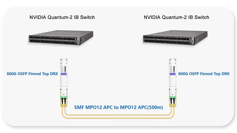
The analysis reveals that optical modules in this configuration account for 52 percent of total power usage by switches. The transceivers, not the switch silicon, dominate the thermal budget. The pattern that exists here represents standard behavior for high-density 800G deployments and shows the necessity of optical thermal planning.
For a 64-port 800G switch, the thermal load doubles:
- Optics: 1,152W (64 × 18W)
- ASIC: ~500W
- Overhead: ~100W
- Total: ~1,752W (5,974 BTU/hr)
Power Trends Impact
The transition from 400G to 800G to 1.6T creates thermal load increases that match the capacity of the system. Each speed generation approximately doubles the power per bit while doubling the bits per port. The net result shows that each generation brings a power increase between 2 times and 2.5 times for every port.
Thermal Planning Implications:
- 400G to 800G migration: Expect 1.5-2x increase in rack thermal load
- 800G to 1.6T migration: Expect 1.5-2x additional increase
- Infrastructure lifecycle: Cooling designed for 400G may be inadequate for 800G, and certainly insufficient for 1.6T
Forward-looking thermal planning should accommodate 30W per port for 1.6T modules. A 32-port switch at 1.6T could generate 1,500W from optics alone, requiring substantial cooling infrastructure.
Data Center Cooling Strategies
Air Cooling Infrastructure
Traditional air cooling remains viable for many OSFP deployments, particularly at 400G and moderate-density 800G configurations.
Standard Hot/Cold Aisle (<20 kW per rack)
Standard data center cooling suffices for deployments below 20 kW per rack. This typically supports:
- Two to three 32-port 800G switches per rack
- Associated servers and storage
- Standard 3-4 m/s airflow through equipment
Requirements for standard air cooling:
- Intake temperature: 18-25°C (65-77°F)
- Airflow velocity: 3-4 m/s through the switch
- Rack clearance: Minimum 6 inches (150mm) front and rear
- Hot aisle/cold aisle containment to prevent recirculation
Rear-Door Heat Exchangers (20-40 kW per rack)
When rack density exceeds 20 kW, rear-door heat exchangers provide an intermediate solution between air and liquid cooling. These water-cooled doors attach to the rear of racks, removing heat before it enters the hot aisle.
- Capital cost: Approximately $5,000 per rack
- Capacity: Up to 40 kW per rack
- Infrastructure: Requires a facility with a chilled water connection
- Benefits: No changes to server or switch hardware; maintains air-cooled equipment compatibility
Rear-door heat exchangers are particularly effective for mixed-density environments where some racks require enhanced cooling while others do not. They enable gradual infrastructure upgrades rather than wholesale facility modifications.
In-Row/In-Rack Cooling (30-50 kW per rack)
For targeted high-density deployments, in-row cooling units place cooling capacity directly adjacent to heat sources. These units:
- Eliminate CRAC (Computer Room Air Conditioner) capacity upgrades
- Provide precise temperature control
- Support densities up to 50 kW per rack
- Capital cost: Approximately $15,000 per unit
In-row cooling is ideal for AI clusters or high-performance computing racks where concentrated heat loads exceed standard cooling capacity.
Liquid Cooling Options
As OSFP power consumption increases, liquid cooling becomes necessary for high-density deployments.
Direct Cold Plate Cooling
Direct liquid cooling attaches cold plates directly to heat-generating components. For OSFP-RHS modules, the cold plate contacts the module’s flat top surface through a thermal interface material, conducting heat to a liquid coolant loop.
Vendors like CoolIT Systems offer dedicated OSFP cold plates (CP-OSFP Series) designed specifically for optical modules. These systems:
- Capture 100% of module heat at the source
- Enable extremely high rack densities (>100 kW per rack)
- Require OSFP-RHS modules (not compatible with IHS)
- Need facility water infrastructure or cooling distribution units
Hybrid Cooling Architectures
Many modern data centers deploy hybrid cooling: liquid-cooled servers connected to air-cooled switches. The system requires precise thermal interface design work to maintain its operational requirements.
NVIDIA’s DGX H100 systems exemplify this approach: liquid-cooled GPU servers connect to air-cooled switches using a mix of OSFP-RHS (in servers) and OSFP-IHS (in switches). The system features a transition from flat-top to finned-top, which happens at the rack level through the implementation of organized cable management and airflow design that maintains sufficient cooling for both operational areas of the system.
Hybrid Cooling Architectures
Modern AI clusters often combine cooling technologies to optimize cost and performance. A typical hybrid architecture might include:
- Liquid cooling: For GPU servers and high-power compute nodes
- Rear-door heat exchangers: For storage and networking racks
- Standard air cooling: For management and low-density infrastructure
The transition between cooling zones requires careful planning. The OSFP modules establish connections between different regions through their two types of flat-top (RHS) and finned-top (IHS) modules, which link liquid-cooled servers to air-cooled switches through fiber connections. The system requires thermal interfaces at both ends to maintain proper cooling functions.
Cooling Strategy Selection Matrix
| Rack Density | Cooling Solution | Capital Cost | Operating Cost | Best For |
| <15 kW/rack | Standard hot/cold aisle | Baseline | Baseline | General 400G/800G deployments |
| 15-25 kW/rack | Enhanced airflow + containment | +20% | +10% | Dense 800G switching |
| 20-40 kW/rack | Rear-door heat exchanger | ~$5K/rack | +15% | High-density retrofits |
| 30-50 kW/rack | In-row cooling | ~$15K/unit | +20% | AI training clusters |
| >50 kW/rack | Direct liquid cooling | Variable | -10% long-term | HPC, extreme density |
Selection Criteria: Consider current density, growth projections, facility constraints, and capital availability. Plan for 1.6T thermal loads even if deploying 800G today, as cooling infrastructure has long lifecycles.
Thermal Planning Calculators
Module Power Budget Calculator
Calculate the annual operating cost of the OSFP module’s power consumption:
Formula:
Annual Power Cost = (Module Power in W) × 8,760 hours × ($/kWh) ÷ 1,000
Example Calculation:
- Module power: 18W
- Electricity rate: $0.12/kWh
- Annual cost: 18 × 8,760 × 0.12 ÷ 1,000 = $18.92 per port per year
For a 32-port switch populated with 18W modules:
- Annual optics power cost: 32 × 18.92=∗∗18.92=∗∗605 per year**
- 5-year TCO impact: $3,025 (power only, not including cooling energy)
LPO Savings Calculation:
- Standard 800G module: 18W → $18.92/year
- LPO 800G module: 8W → $8.41/year
- Annual savings per port: $10.51
- 32-port switch annual savings: $336
Rack Thermal Budget Worksheet
Use this worksheet to calculate the total rack thermal load:
| Component | Calculation Method | Example Values | Subtotal |
| OSFP Optics | Ports × Module Watts | 64 ports × 18W | 1152W |
| Switch ASICs | Count × ASIC TDP | 2 switches × 450W | 900W |
| Servers | Count × Server TDP | 8 servers × 350W | 2800W |
| Storage | Count × Array TDP | 2 arrays × 200W | 400W |
| Network Overhead | Fans, PDUs, etc. | 10% of the above | 525W |
| TOTAL POWER | 5,777W | ||
| HEAT OUTPUT | Watts × 3.41 | 5,777 × 3.41 | 19,700 BTU/hr |
Cooling Capacity Check:
- Required cooling: 19,700 BTU/hr ÷ 3.41 = 5.8 tons
- Standard CRAC capacity: 5-20 tons per unit
- Assessment: Marginal for standard cooling; consider enhancement
Thermal Headroom Calculator
Always plan for headroom in thermal calculations to accommodate peak loads, future growth, and unexpected conditions.
Headroom Guidelines:
- Minimum: 20% headroom for peak traffic loads
- Recommended: 30% headroom for growth and safety
- Future-proofing: 50% headroom if planning 1.6T migration
Calculation Example:
- Calculated load: 5,777W
- With 30% headroom: 5,777 × 1.30 = 7,510W required capacity
- With 50% headroom: 5,777 × 1.50 = 8,666W required capacity
Temperature Headroom:
- Maximum module operating temperature: 70°C
- Recommended alarm threshold: 65°C
- Target operating temperature: 45-55°C
- Headroom: 15-25°C below maximum for reliability
Cooling Cost Comparison
Compare total cost of ownership for different cooling approaches over a 5-year lifecycle:
| Cost Component | Air Cooling | Rear-Door HX | Direct Liquid |
| Initial Infrastructure | Baseline | +$5K/rack | +$20K/rack |
| Annual Energy | Baseline | -10% | -30% |
| Maintenance | Baseline | +$500/year | +$1,000/year |
| 5-Year TCO | Baseline | +$2,500 | -$5,000 |
Note: Actual costs vary by facility, location, and scale. Liquid cooling shows TCO advantages at high densities due to energy savings.
Deployment Best Practices
Pre-Deployment Verification Checklist
Complete this checklist before OSFP deployment to avoid thermal issues:
Cage and Module Verification:
Confirm switch cage types (IHS vs RHS) from manufacturer specifications
Verify ordered modules match cage types
Check module power ratings against switch power supply capacity
Validate thermal interface specifications for RHS deployments
Cooling Infrastructure Verification:
Calculate the total rack heat load using the worksheet above
Verify cooling capacity meets requirements with headroom
Confirm airflow direction matches switch design (front-to-rear, rear-to-front, or side-to-side)
Check rack spacing: minimum 6 inches front and rear clearance
Verify data center ambient temperature < 25°C (77°F)
Power Infrastructure Verification:
Calculate total rack power draw
Verify PDU capacity with 20% headroom
Confirm circuit capacity for inrush currents during switch boot
Plan for redundant power feeds if required
Documentation:
Record baseline thermal measurements before deployment
Document module types and serial numbers
Create a rack thermal map showing equipment layout
Establish temperature monitoring baselines
Installation Guidelines
Proper installation prevents many thermal issues:
ESD Protection:
- Always use grounded wrist straps when handling OSFP modules
- Store modules in anti-static packaging until installation
- Work in ESD-safe environments with 40-60% relative humidity
Module Handling:
- Remove protective dust caps only when ready to insert
- Verify proper module orientation before insertion
- Push firmly until the latch engages (audible click)
- For IHS modules, verify thermal pad contact with the cage heat sink
- For RHS modules, verify the TIM application per the manufacturer’s specification
Cable Management:
- Maintain a minimum 30mm bend radius for fiber cables
- Secure cables to prevent strain on module connectors
- Use cable management to prevent blocking airflow
- Label cables for easy identification during troubleshooting
Airflow Management:
- Install blanking panels in empty switch slots
- Ensure no cables obstruct air intakes or exhausts
- Verify hot aisle/cold aisle containment integrity
- Check for air recirculation around rack edges
Temperature Monitoring Setup
Implement comprehensive thermal monitoring from day one:
Module-Level Monitoring:
- Enable DOM (Digital Optical Monitoring) or CMIS telemetry
- Poll module temperature every 60 seconds
- Set alert threshold at 65°C
- Set alarm threshold at 70°C
- Log historical data for trend analysis
Switch-Level Monitoring:
- Monitor intake and exhaust air temperatures
- Track fan speeds and power consumption
- Correlate temperature with traffic load
- Set environmental alarms for out-of-range conditions
Threshold Guidelines:
| Parameter | Warning | Critical | Emergency |
| Module Temperature | 65°C | 70°C | 75°C |
| Intake Air Temperature | 27°C | 30°C | 32°C |
| Fan Speed (% max) | 80% | 90% | 100% |
For detailed installation procedures, see our 400G OSFP implementation guide.
Troubleshooting Thermal Issues
Common Thermal Problems and Solutions
| Symptom | Likely Cause | Solution |
| Thermal alarms on multiple modules | Insufficient rack cooling | Check CRAC operation, verify rack spacing, and inspect air filters |
| Gradual temperature increase over weeks | Filter clog or fan degradation | Replace air filters, verify fan RPM, and check for dust buildup |
| Hot spots at the rear of the switch | Heat trapping, poor airflow | Verify blanking panels installed, check for cable obstruction |
| Single module thermal alarm | Module defect or poor seating | Reseat module, verify thermal interface, replace if persistent |
| Link flapping during peak hours | Thermal throttling from overheating | Immediate cooling check, reduce traffic temporarily, add cooling |
| High temperatures after maintenance | Reversed airflow or blocked vents | Verify switch orientation, check all vents clear, and confirm fan direction |
Thermal Troubleshooting Decision Tree
Start: Thermal Alarm Detected
Check alarm scope
- Single module → Go to 2
- Multiple modules → Go to 3
- All modules → Go to 4
Single module issue
- Reseat the module firmly
- Check fiber connector cleanliness
- Verify module power rating matches the application
- Replace the module if the issue persists
Multiple module issue
- Check the rack cooling system status
- Verify air filters are clean
- Confirm no recent changes to the rack layout
- Measure intake air temperature
All modules hot
- Verify facility cooling operational
- Check switch fan operation
- Confirm the airflow direction is correct
- Inspect for blocked vents or recirculation
Temperature Trend Analysis:
Gradual temperature increases over days or weeks typically indicate:
- Air filter clogging (check and replace)
- Fan degradation (monitor RPM, replace if slow)
- Seasonal ambient temperature changes (adjust CRAC setpoints)
- Dust buildup (schedule cleaning)
Sudden temperature spikes typically indicate:
- Cooling system failure (emergency response)
- Airflow blockage (immediate inspection)
- Configuration change affecting traffic (review recent changes)
- Fan failure (replace immediately)
Emergency Procedures
If module temperatures exceed 75°C:
Immediate actions:
- Reduce traffic load if possible
- Increase facility cooling capacity
- Open rack doors temporarily (if recirculation is not a concern)
- Deploy portable cooling if available
Short-term remediation:
- Identify and replace any failed fans
- Clean or replace air filters
- Verify all modules are properly seated
- Check for firmware updates that might improve power efficiency
Long-term solutions:
- Upgrade cooling infrastructure if chronic issue
- Redistribute equipment to reduce rack density
- Consider LPO modules to reduce power consumption
- Plan migration to liquid cooling if density continues increasing
Future-Proofing for 1.6T
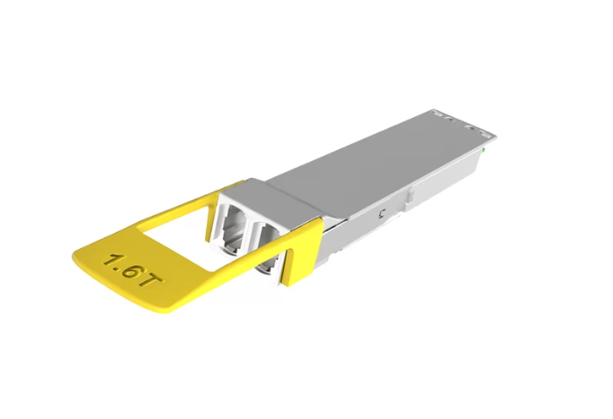
1.6T Thermal Requirements
The transition to 1.6T OSFP modules will significantly increase thermal loads. Early specifications and industry projections indicate:
Power Consumption Projections:
- 1.6T DR8 modules: 25-30W per module
- 1.6T ZR/ZR+ coherent: 30-33W per module
- Fully-populated 32-port switch: 800-1,000W from optics alone
Thermal Design Implications:
- Air-cooled switches at 1.6T will require enhanced airflow (4-5 m/s)
- Rack densities above 20 kW will likely require liquid cooling
- Standard data center cooling may be inadequate for dense 1.6T deployments
Infrastructure Planning:
When deploying 800G infrastructure today, consider 1.6T thermal requirements:
- Specify cages with thermal headroom for 30W modules
- Plan cooling capacity for 50% higher thermal loads
- Design cable management for higher-density fiber
- Consider liquid cooling readiness, even if initially air-cooled
Emerging Cooling Technologies
Advanced Thermal Interface Materials
Next-generation TIMs improve heat transfer between modules and cooling systems:
- Metal-based TIMs: >10 W/mK thermal conductivity
- Phase change materials (PCM): Honeywell PTM7950 and similar
- No oil bleed formulations for long-term reliability
These materials are particularly important for RHS modules where TIM quality directly impacts cooling efficiency.
Co-Packaged Optics (CPO)
CPO places optical engines directly on switch ASIC packages, eliminating pluggable modules. This approach:
- Reduces power consumption by 40-50% compared to pluggable optics
- Increases port density significantly
- Requires liquid cooling for the integrated optical/ASIC assembly
- Changes serviceability (module replacement not possible)
CPO deployment is expected in 2026-2027 for the highest-density AI clusters. Organizations planning 5+ year infrastructure lifecycles should monitor CPO development, though pluggable OSFP remains the practical choice for most deployments through 2028.
Immersion Cooling
Two-phase immersion cooling submerges entire servers in dielectric fluid, enabling extreme rack densities (>250 kW per rack). For OSFP applications:
- Requires a specialized module sealing
- Provides ultimate thermal performance
- Significant infrastructure investment is required
- Primarily for hyperscale AI training facilities
For more on 1.6T technology planning, see our 1.6T OSFP complete guide.
Frequently Asked Questions
How hot do OSFP modules run?
The operational temperature range for OSFP modules ranges from 45 to 55 degrees Celsius, which converts to 113 through 131 degrees Fahrenheit. The maximum operating temperature for the system reaches 70 degrees Celsius, which equals 158 degrees Fahrenheit, while the system generates alerts when temperatures reach 65 degrees Celsius. The OSFP modules operate 2 to 3 degrees Celsius hotter than QSFP-DD modules because they consume more power, but their larger heat sink area enables superior thermal control.
What cooling do I need for 800G OSFP?
For 800G OSFP deployments, standard air cooling suffices for densities below 20 kW per rack. The system requires airflow between 3 and 4 meters per second through switches, together with intake temperatures that must remain below 25 degrees Celsius, and proper rack spacing, which needs 6 inches for front and rear access. For densities above 20 kW, consider rear-door heat exchangers or in-row cooling. The system requires liquid cooling for system operations which exceed 50 kilowatts per rack or for 1.6T system deployments.
Should I choose IHS or RHS for my deployment?
The OSFP-IHS system serves as the best option for traditional air-cooled data centers, which use standard switch infrastructure from vendors like Arista, Cisco, or Juniper. Select OSFP-RHS for liquid-cooled environments, high-density AI clusters, or NIC/DPU deployments. The same cage type should never include IHS and RHS systems. The IHS system offers better deployment options, which apply to most data center environments.
When should I consider liquid cooling for OSFP?
You should implement liquid cooling on OSFP systems when two conditions become true. Liquid cooling becomes necessary when rack power density reaches 50 kW and users need to operate 1.6T modules. Liquid cooling becomes necessary when facility operators need to establish air conditioning systems as their only operational option. Energy efficiency requirements drive organizations to use liquid cooling systems, which increase their operational expenses but need less facility space.
What temperature thresholds should I set for monitoring?
The recommended thermal monitoring thresholds define three warning levels, which include a warning at 65°C and a critical alarm at 70°C, and an emergency shutdown consideration at 75°C. The target operating temperature for optimal reliability needs to be maintained between 45°C and 55°C. The system should trigger intake air temperature alerts at 27°C and critical alerts at 30°C. The system must maintain a temperature difference of 15°C between its normal operating temperature and its maximum rated temperature.
Conclusion
OSFP thermal management requires planning at multiple levels: module selection, switch configuration, rack design, and facility cooling. A single dense switch produces more than 1 kW of heat, which leads to substantial thermal loads, and this problem increases with each successive speed generation.
Key takeaways for your thermal planning:
- Plan for real power numbers: Datasheet typicals underestimate real-world consumption by 15-25%. Use maximum power specifications for thermal calculations.
- Choose the right thermal design: IHS for air-cooled flexibility, RHS for liquid-cooled efficiency. Verify cage compatibility before ordering modules.
- Calculate complete thermal loads: Include optics, switch silicon, and overhead. Optical modules often represent 50% or more of total power consumption.
- Headroom design: Plan 30% thermal headroom for peak loads and future growth. Infrastructure lasts longer than individual equipment generations.
- Monitor continuously: Implement temperature monitoring from day one. Thermal issues develop gradually—trending data enables proactive intervention.
The transition to 800G and 1.6T is driving data centers toward liquid cooling and higher densities. Organizations that master OSFP thermal management today will be prepared for the networking demands of tomorrow.
Ready to plan your OSFP thermal infrastructure? Contact FiberMall for thermal design consultation and explore our 800G OSFP modules engineered for reliable high-temperature operation.
Related Articles:
Complete Guide to OSFP Transceivers
OSFP Data Center Deployment Guide
800G OSFP Performance Analysis
400G OSFP Implementation Guide
Related Products:
-
 NVIDIA MMA4Z00-NS400 Compatible 400G OSFP SR4 Flat Top PAM4 850nm 30m on OM3/50m on OM4 MTP/MPO-12 Multimode FEC Optical Transceiver Module
$400.00
NVIDIA MMA4Z00-NS400 Compatible 400G OSFP SR4 Flat Top PAM4 850nm 30m on OM3/50m on OM4 MTP/MPO-12 Multimode FEC Optical Transceiver Module
$400.00
-
NVIDIA MMS4X00-NS400 Compatible 400G OSFP DR4 Flat Top PAM4 1310nm MTP/MPO-12 500m SMF FEC Optical Transceiver Module
$450.00
-
NVIDIA MMA1Z00-NS400 Compatible 400G QSFP112 VR4 PAM4 850nm 50m MTP/MPO-12 OM4 FEC Optical Transceiver Module
$385.00
-
NVIDIA MMS1X00-NS400 Compatible 400G NDR QSFP112 DR4 PAM4 1310nm 500m MPO-12 with FEC Optical Transceiver Module
$500.00
-
NVIDIA MMA4Z00-NS Compatible 800GBASE 2 x SR4/SR8 OSFP PAM4 850nm 100m DOM Dual MPO-12 MMF Optical Transceiver Module
$550.00
-
NVIDIA MMA4Z00-NS-FLT Compatible 800GBASE 2 x SR4/SR8 OSFP RHS/Flat Top PAM4 850nm 100m DOM Dual MPO-12 MMF Optical Transceiver Module
$600.00
-
NVIDIA MMS4X00-NM Compatible 800GBASE 2 x DR4/DR8 OSFP IHS/Closed Finned Top PAM4 1310nm 500m DOM Dual MTP/MPO-12 SMF Optical Transceiver Module
$600.00
-
NVIDIA MMS4X00-NM-FLT Compatible 800GBASE 2 x DR4/DR8 OSFP Flat Top PAM4 1310nm 500m DOM Dual MTP/MPO-12 SMF Optical Transceiver Module
$650.00
-
NVIDIA MMS4X50-NM Compatible 800G 2x FR4 OSFP IHS/Closed Finned Top PAM4 1310nm 2km DOM Dual Duplex LC SMF InfiniBand NDR Optical Transceiver Module
$1000.00
-
NVIDIA MMS4A00 (980-9IAH1-00XM00) Compatible 1.6T 2 x DR4/DR8 OSFP224 PAM4 1311nm 500m IHS/Finned Top Dual MPO-12 SMF Optical Transceiver Module
$1500.00
-
NVIDIA MMS4A50 Compatible 1.6T 2xFR4/FR8 OSFP224 PAM4 1310nm 2km IHS/Finned Top Dual Duplex LC SMF Optical Transceiver Module
$1800.00
-
NVIDIA MMS4A00-RHS Compatible 1.6T 2xDR4/DR8 OSFP224 PAM4 1311nm 500m RHS/Flat Top Dual MPO-12/APC InfiniBand XDR SMF Optical Transceiver Module
$2000.00