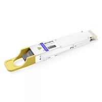
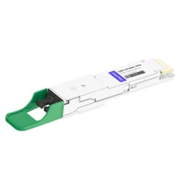
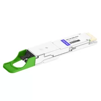
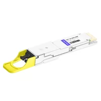
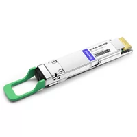
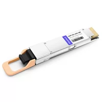
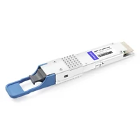
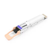
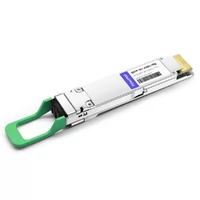
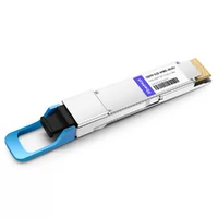
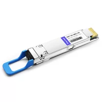
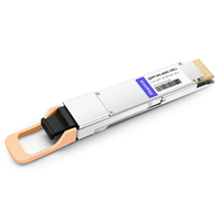
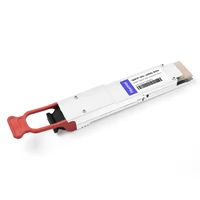
Sarah observed the dashboard which showed the red light for the third instance during that morning. The inspection showed that ports 17 through 24 had experienced another outage, which followed a definite pattern. The same ports always show outages, which occur at the same time when outdoor temperatures reach their highest point. She discovered that her 800G QSFP-DD modules, which she had just purchased, experienced thermal throttling because she had not anticipated this problem.
The deployment appeared flawless according to the project documentation. The system used completely new switches together with first-rate modules and sufficient power distribution units. The design failed to consider that 32 ports of 800G optics create 544 watts of heat which affects a single 1U switch and exceeds the capacity of her data center’s airflow system.
The process of module power evaluation serves as an essential element that designers must include in their deployment plans. It serves as an essential design factor that impacts the total rack space, cooling equipment needs, and selection of modules. The guide provides you with precise values together with calculation methods that enable you to effectively plan power and thermal needs from the initial attempt.

The course content will teach you about power class definitions together with specific energy use of each module and methods to calculate power at the rack level and how thermal throttling operates and ways to stop it and methods for choosing between air and liquid cooling and AI cluster power density and TCO module selection analysis.
New to QSFP-DD? Start with our complete QSFP-DD guide for fundamentals.
QSFP-DD Power Classes and Specifications
Power class isn’t just a label—it’s a thermal design constraint.
The QSFP-DD MSA defines specific power classes that switch vendors use to size cooling and power delivery. When a switch port supports “up to Class 8,” that’s a thermal commitment from the switch designer. Push beyond that, and modules either won’t power up or will throttle aggressively.
MSA Power Class Definitions
QSFP-DD power classes range from low single-digit watts to over 18W per module:
| Power Class | Max Power | Typical Module Types |
| Class 1-2 | ≤2.5W | Legacy 100G QSFP+ adapters |
| Class 3-4 | 2.5-5W | 200G modules |
| Class 5-6 | 5-10W | 400G modules (most types) |
| Class 7 | 10-14W | 400G long-reach, early 800G |
| Class 8 | 14-18W | 800G modules (most types) |
| Higher | 18W+ | Coherent 800G ZR/ZR+ |
Most production switches today support Class 8, providing up to 18W per port. Some newer platforms support 20W+ for coherent modules. Always verify your switch’s port-level power capability before specifying high-power modules.

Power Consumption by Module Type
Real-world QSFP-DD power consumption varies significantly by module type:
- 400G-SR8: 8-9W (multimode, 100m)
- 400G-DR4: 9-10W (single-mode, 500m)
- 400G-FR4: 10-11W (single-mode, 2km)
- 400G-LR4: 12-14W (single-mode, 10km)
800G QSFP-DD modules:
- 800G-SR8: 13-14W (multimode, 100m)
- 800G-DR8: 15-16W (single-mode, 500m)
- 800G-2FR4: 16-17W (single-mode, 2km)
- 800G-LR4: 17-18W (single-mode, 10km)
These are typical operating values. Peak power during link establishment can run 10-15% higher.
Power vs Reach Trade-offs
Longer distance capabilities of a system usually result in increased power requirements. The DSP and laser drivers needed for a 10km reach consume more than short-reach equivalents. A 400G-LR4 module pulls roughly 50% more power than a 400G-SR8.
The 400G ZR and 800G ZR coherent modules require power consumption between 18W and 25W because they perform advanced DSP functions. Data center operations require them for DCI applications but they remain infrequently deployed within the data center.
The pattern matters: matching reach to actual requirements saves substantial power across hundreds of ports.
QSFP-DD Rack-Level Power Calculations
Most rack power planning forgets the optics.
Designers calculate switch power together with server power and storage power. The process concludes with the addition of optics as an afterthought. The afterthought transforms into a vital component because 800G QSFP-DD requires 17W power for each port.
Marcus discovered this important lesson while constructing his AI cluster. He intended to build a training cluster with 32 racks, which would use 64-port 800G spine switches. His first design used 8kW PDUs which he based on the specifications of switches and servers. The power calculation for optic components produced different results when he performed the calculation as an independent task.
The optic system consumed 1,088W for the 64 ports of 800G, which operated at 17W average. The system required 1.4kW of power to run the switch ASIC and fans. Each spine required 2.5kW of power because we installed two spines at every rack location. The installation of GPU servers made our existing 8kW PDUs insufficient for demand. He implemented a 12kW PDU upgrade before he started his deployment. The system experienced no PDU trips during a time period of 18 months.
Power Calculation Framework
Calculate rack power for QSFP-DD deployments systematically:
Step 1: Inventory ports per device
Count exact port populations. Don’t assume full population—half-populated switches are common during gradual migration.
Step 2: Identify module types per port
Different ports may use different modules. Document each.
Step 3: Sum module power
Multiply port count by typical power per module type. Use upper-range values (17W for 800G, not 14W) for safety margin.
Step 4: Add switch ASIC power
Switch silicon consumes 0.5-2kW depending on platform. Check vendor datasheets.
Step 5: Add fan power
Fans typically draw 100-400W. Higher under thermal load.
Step 6: Apply cooling overhead
Every watt of equipment power needs cooling. Factor 1.4-1.8x for traditional air-cooled facilities (PUE consideration).
Sample Calculations
32-port 800G spine (typical):
- Optics: 32 × 17W = 544W
- ASIC: 1,200W
- Fans: 200W
- Total switch: 1,944W
- With cooling overhead (1.5x): ~2.9kW
64-port 400G leaf (typical):
- Optics: 64 × 10W = 640W
- ASIC: 800W
- Fans: 150W
- Total switch: 1,590W
- With cooling overhead: ~2.4kW
AI cluster spine (high-density):
- Optics: 64 × 17W = 1,088W
- ASIC: 1,400W
- Fans: 300W
- Total switch: 2,788W
- With cooling overhead: ~4.2kW
PDU Sizing Considerations
Size PDUs with 20-30% headroom above calculated power. This handles:
- Peak power during link establishment
- Higher inlet temperatures driving fan ramp
- Future module upgrades
For redundant deployments, size each PDU to handle full load if its partner fails. A/B power feeds at 50% utilization each can absorb a single feed failure without exceeding capacity.
For 800G-specific deployment guidance, see our 800G QSFP-DD deployment guide.
QSFP-DD Thermal Management and Throttling
Modules don’t slow down when they overheat—they shut off.
Engineers face unexpected challenges. Many people think that thermal protection causes equipment performance to decline at a slow pace. QSFP-DD modules function with a binary operation system. The module operates normally until case temperature exceeds the throttling threshold, then it disables the port to protect itself.
Carlos encountered this problem. His new 800G modules ran perfectly during cold-aisle commissioning. The ports began to malfunction at peak times three weeks after production started. “DOM data showed case temperatures at 72-74°C right before each shutdown. The throttling threshold, which we operated at 4°C above normal position, required us to maintain temperatures at 70°C.
His diagnosis revealed that insufficient hot-aisle return airflow caused the problem. The recirculation of hot air to the cold aisle generated increased inlet temperature, which caused the modules to exceed their thermal capacity. The installation of blanking panels together with better containment systems resulted in temperature reduction to specification levels. The modules maintained stable operations.
How Thermal Throttling Works
QSFP-DD modules monitor case temperature continuously. When case temp exceeds the manufacturer’s threshold (typically 70-75°C):
- Warning state: Module reports high temperature via DOM
- Switch fan ramp: Switch increases fan speeds to add cooling
- Throttle threshold: Module disables transmitter
- Port reset: Switch may attempt port restart after cool-down
The behavior varies slightly by vendor, but the binary nature is consistent. Either the module operates fully or it doesn’t operate at all.
Common Thermal Issues
Inlet temperature too high:
- ASHRAE A1 recommends 18-27°C inlet
- Hot air recirculation raises inlet temperatures
- Each 1°C of additional inlet directly raises case temp
Inadequate airflow:
- Fan failures reduce cooling capacity
- Cable obstructions block airflow paths
- Missing blanking panels allow recirculation
High port density:
- Fully-populated 800G switches concentrate heat
- 32 × 17W = 544W in a 1U switch
- Adjacent equipment increases ambient temperature
Cable management:
- Bundled fiber cables block exhaust airflow
- Improperly routed cables create hot spots

Preventing Thermal Throttling
Build in thermal margin during design:
- Monitor inlet temperatures at the rack level, not just facility level
- Verify airflow paths with actual deployed equipment, not just design assumptions
- Read DOM data weekly to spot trending case temperature increases
- Install blanking panels to prevent hot air recirculation
- Plan for fan failures with N+1 redundancy where possible
Pre-emptive monitoring catches thermal issues before they cause outages. Set alerts at 5°C below throttling thresholds.
For switch-specific thermal behavior, our QSFP-DD compatibility guide covers vendor differences.
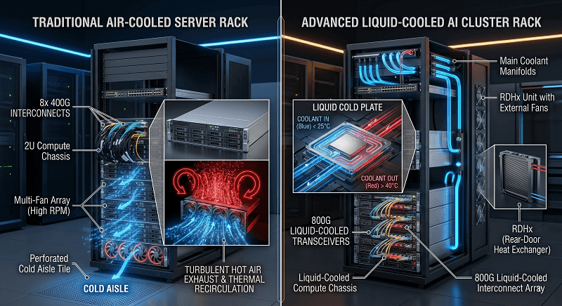
Air Cooling vs Liquid Cooling for QSFP-DD
When does air cooling stop being enough?
The answer depends on rack power density, not just total facility cooling capacity. A facility might have abundant cooling overall but lack the airflow to remove heat from a high-density rack. The incorrect selection of cooling methods based on your density requirements will result in thermal problems that require costly retrofitting solutions.
Air Cooling Capabilities
Standard air cooling handles rack power densities up to about 15kW with proper design. Beyond that, several factors limit effectiveness:
Containment systems:
- Hot aisle/cold aisle separation: handles 8-12kW racks
- Hot aisle containment: extends to 12-15kW
- Cold aisle containment: similar range
- Curtains and end-caps required for higher densities
Airflow rate limits:
- CFM per kW determines cooling capacity
- Standard CRAC units: ~150 CFM per kW
- Beyond 15kW, needed CFM exceeds practical airflow
Acoustic limits:
- Higher airflow requires higher fan speeds
- Acoustic levels exceed safety thresholds at extreme densities
Liquid Cooling Approaches
Several liquid cooling options address higher power densities:
Rear-door heat exchangers (RDHX):
- Mount on rack rear door
- Capacity: 15-30kW per rack
- Air-cooled equipment, water removes heat at exhaust
- No equipment modification required
Direct liquid cooling (cold plate):
- Liquid flows through equipment cold plates
- Capacity: 30-100kW per rack
- Requires liquid-cooled servers/switches
- Optics still typically air-cooled within liquid-cooled systems
Immersion cooling:
- Equipment submerged in dielectric fluid
- Capacity: 100kW+ per rack
- Limited optic compatibility today
- Emerging for AI clusters
QSFP-DD modules themselves remain primarily air-cooled in 2026, even within liquid-cooled deployments. The switch chassis cools the optics with airflow while liquid cooling handles the ASIC.
Decision Framework
Match cooling approach to rack power density:
| Rack Power | Recommended Cooling |
| <10kW | Standard air cooling |
| 10-15kW | Enhanced air with containment |
| 15-30kW | Rear-door heat exchangers |
| 30-50kW | Direct liquid cooling |
| >50kW | Liquid + immersion considerations |
For AI clusters typically running 25-40kW per rack, RDHX or direct liquid cooling are practical requirements, not luxury options.
Our QSFP-DD for AI cluster networking guide covers AI-specific cooling strategies.
AI Cluster Power Density
AI clusters break traditional rack power assumptions.
Data center racks should operate at 5 to 10 kilowatts of power. The power consumption of AI clusters operates between 25 and 40 kilowatts for each rack. The combination of dense GPU servers, multiple high-bandwidth network connections, and 800G optics creates power densities that existing facilities need to undergo major modifications for proper operation.
GPU Cluster Power Profile
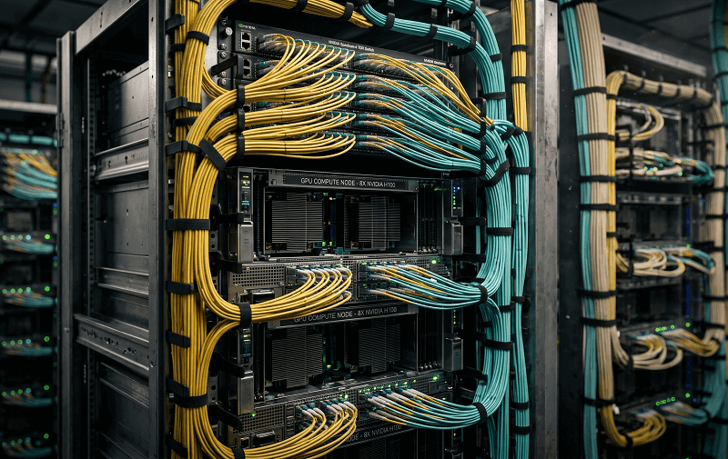
A typical AI training rack contains:
8-GPU server (HGX H100 or similar):
- Server power: 6-10kW per server
- Network connections: 8-16 ports per server
- Per-server optics: 8 × 17W = 136W (eight 800G ports)
Rack composition:
- 4-6 GPU servers per rack
- Total compute power: 24-60kW
- Total optic power: 600-800W
- Plus ToR switch power: 2-3kW
Total rack power: 28-65kW depending on configuration.
Spine Switch Power Requirements
AI cluster spine switches concentrate enormous optic counts:
64-port 800G spine:
- 64 × 17W = 1,088W in optics alone
- Plus 1.4kW ASIC and 300W fans
- Total: ~2.8kW per switch
128-port 800G spine (newer platforms):
- 128 × 17W = 2,176W in optics
- Plus higher ASIC power: ~2kW
- Total: ~4.5kW per switch
In a multi-rail Clos fabric with 8 spines, total spine power approaches 25-40kW just for the network. This is independent of the GPU compute power.
Hyperscaler Best Practices
Major AI cluster operators have developed specific approaches:
Dedicated AI rooms:
- Higher cooling capacity per rack (30-50kW)
- Liquid-cooled GPUs with air-cooled optics
- Reinforced power distribution (415V/240V phases)
Phased deployment:
- Start with partial rack population
- Validate thermal performance under load
- Expand to full density only after validation
Module selection optimization:
- Use SR8 (multimode) for in-rack connections
- Reserve DR8/FR4 for cross-row links
- Avoid coherent optics inside the cluster
These practices keep optic power manageable even as overall rack density grows.
Power Cost Analysis
Module power costs add up faster than you think.
Operating power expenses often exceed module purchase costs over a 5-year lifecycle. This is rarely calculated during procurement, leading to surprise budget pressures in operations.
Calculating Annual Power Cost
The basic formula for annual power cost per module:
Power × Hours × kWh Rate × Cooling Multiplier
For a typical 800G module:
- 17W × 8,760 hours × 0.12/kWh=0.12/kWh=17.87 base power cost
- Cooling overhead (1.5x PUE): $26.80 total annual cost
Across 1,000 modules: $26,800 per year just for optic power and cooling.
Module Selection for Power Efficiency
Substantial savings come from matching module reach to actual requirements:
| Module Pair | Power Difference | Annual Cost Difference (per module) |
| 800G-SR8 vs 800G-DR8 | 2W | ~$3.15 |
| 800G-DR8 vs 800G-2FR4 | 1W | ~$1.58 |
| 800G-2FR4 vs 800G-LR4 | 1.5W | ~$2.36 |
These differences seem small per module. At the deployment scale, they compound:
Example: 1,000 in-rack connections
- All DR8: $24,500/year power cost
- All SR8 (where reach allows): $20,400/year
- Savings: 4,100/year,4,100/year,20,500 over 5 years
Long-Term TCO Considerations
Total cost of ownership includes:
- Module purchase price
- 5-year power costs
- 5-year cooling overhead
- Cooling infrastructure investment
For high-density deployments, cooling infrastructure can exceed module purchase costs over a decade. Plan for this in procurement decisions, not just initial pricing.
Power-Optimized Module Selection
Match module power to actual reach requirements.
The default tendency is to over-spec reach. “Just in case” thinking adds cost without benefit. Power-optimized selection means choosing the lowest-power module that meets the reach requirement.
Selection Decision Tree
For each connection, work through this sequence:
1. Determine actual reach
- Measure cable run including service loops
- Add 20% margin for routing changes
- Compare to module reach specifications
2. Identify minimum-reach module
- 100m or less: Multimode (SR8) – lowest power
- 100-500m: DR4/DR8 – moderate power
- 500m-2km: 2FR4/FR4 – moderate power
- 2-10km: LR4 – higher power
- 10-40km: ER4 – highest power
3. Verify power budget
- Confirm switch supports module power class
- Check rack power calculations include this choice
- Validate cooling capacity at chosen density
4. Consider TCO
- Calculate 5-year power cost difference
- Factor cooling infrastructure impact
- Compare against any reach margin benefits
Common Power-Saving Wins
Patterns that yield significant savings:
SR8 for in-rack connections when both endpoints share a rack. Saves 2-4W per port over longer-reach options.
2FR4 instead of LR4 for cross-row data center connections. The 2km reach handles most data center distances.
Avoid coherent optics inside the data center. ZR/ZR+ modules are designed for DCI distances (40-120km) and waste power on shorter spans.
For module-specific selection guidance, see our 400G QSFP-DD module types guide. For power-optimized 800G modules validated across major switch platforms, explore the FiberMall 800G QSFP-DD product line.
FAQ
How much power does an 800G QSFP-DD module use?
The standard power consumption range for 800G QSFP-DD modules lies between 14 to 18 watts during their regular functioning. The power consumption of SR8 modules ranges from 13 to 14 watts while DR8 modules require 15 to 16 watts and 2FR4 modules need 16 to 17 watts and LR4 modules draw between 17 to 18 watts. The maximum power consumption of Coherent ZR/ZR+ modules reaches 25 watts. The actual specifications of a product should always be confirmed through vendor datasheets.
What power difference exists between SR8 and DR8 modules?
SR8 modules typically use 2-3W less power than DR8 modules. The 800G SR8 system operates at an average power consumption level of 13 to 14 watts while the 800G DR8 system operates at an average power consumption level of 15 to 16 watts. The power difference between SR8 and DR8 modules results in considerable yearly energy and cooling savings across multiple ports which makes SR8 the preferred option for distances up to 100 meters.
What causes my QSFP-DD modules to experience thermal throttling issues?
Thermal throttling begins when the module case temperature exceeds the designated safety limit which usually stays between 70 and 75 degrees Celsius. The system experiences common failures from multiple factors which include high inlet air temperature and inadequate airflow and hot air recycling and fan breakdowns and too many active ports. The DOM data should be checked to determine case temperatures while comparing your actual airflow design to the operational conditions.
Do I need liquid cooling for 800G QSFP-DD modules?
Liquid cooling is not required to operate the 800G QSFP-DD modules’. High-density racks that have total power above 15kW need liquid cooling systems to operate effectively. The rear-door heat exchangers at 15-30kW racks function with all necessary components. The switch ASIC receives direct liquid cooling while the QSFP-DD modules remain air-cooled inside the chassis. AI clusters running between 30 to 40 kilowatts require liquid cooling systems.
What is the process to determine rack power requirements for QSFP-DD installations?
The required power for multiple modules should be calculated by multiplying the number of ports with the specified wattage for each module type and then including the switch ASIC power together with the fan power while using a cooling overhead between 1.4 to 1.8 times the total. The 64-port 800G spine consumes 1,088W through optics and 1.4kW through ASIC and 300W through fans to achieve a total power consumption of 2.8kW. The cooling overhead requires you to allocate 4 to 4.5kW spine power into your rack budget.
Conclusion
Sarah’s thermal throttling story isn’t unusual. It happens because power and thermal planning often gets attention only after problems emerge. The fix takes hours of troubleshooting and sometimes infrastructure changes that should have happened during initial design.
Key takeaways:
- Calculate optic power explicitly—don’t bundle it with switch power estimates
- Match module reach to actual requirements—over-specification wastes power and money
- Plan thermal margin into airflow design—5°C of headroom prevents most throttling issues
- Match cooling to rack density—above 15kW, air cooling alone struggles
- Factor 5-year operating costs—module power costs compound at deployment scale
- AI clusters need different planning—30-40kW racks require fundamentally different infrastructure
QSFP-DD power and thermal challenges are solvable with the right planning. The calculation frameworks and decision criteria in this guide prevent the surprises that derail deployments. Use them during design, not after problems appear.
Ready to plan your QSFP-DD deployment power and thermal requirements? Contact FiberMall’s technical team for power calculation assistance, module selection optimization, and thermal design guidance. We’ve validated power and thermal performance across hundreds of data center deployments—helping you avoid the surprises that turn smooth rollouts into emergency response.
Explore our 800G QSFP-DD product line for power-optimized modules.
Looking ahead, 1.6T transceivers will push power consumption to 25W+ per port. The frameworks in this guide apply directly to that next generation. Plan now using these principles, and 1.6T deployments become incremental rather than revolutionary.
Related Products:
-
 QSFP-DD-800G-DR8 800G-DR8 QSFP-DD PAM4 1310nm 500m DOM MTP/MPO-16 SMF Optical Transceiver Module
$1000.00
QSFP-DD-800G-DR8 800G-DR8 QSFP-DD PAM4 1310nm 500m DOM MTP/MPO-16 SMF Optical Transceiver Module
$1000.00
-
QSFP-DD-800G-FR8 QSFP-DD 8x100G FR PAM4 1310nm 2km DOM MPO-16 SMF Optical Transceiver Module
$1200.00
-
QSFP-DD-800G-2FR4 800G QSFP-DD 2FR4 PAM4 1310nm 2km DOM Dual CS SMF Optical Transceiver Module
$1900.00
-
QSFP-DD-800G-2FR4L QSFP-DD 2x400G FR4 PAM4 CWDM4 2km DOM Dual duplex LC SMF Optical Transceiver Module
$1800.00
-
QSFP-DD-800G-DR8D QSFP-DD 8x100G DR PAM4 1310nm 500m DOM Dual MPO-12 SMF Optical Transceiver Module
$1000.00
-
QSFP-DD-800G-FR8L QSFP-DD 800G FR8 PAM4 CWDM8 2km DOM Duplex LC SMF Optical Transceiver Module
$3000.00
-
QSFP-DD-400G-SR8 400G QSFP-DD SR8 PAM4 850nm 100m MTP/MPO OM3 FEC Optical Transceiver Module
$149.00
-
QSFP-DD-400G-DR4 400G QSFP-DD DR4 PAM4 1310nm 500m MTP/MPO SMF FEC Optical Transceiver Module
$400.00
-
QSFP-DD-400G-SR4 QSFP-DD 400G SR4 PAM4 850nm 100m MTP/MPO-12 OM4 FEC Optical Transceiver Module
$450.00
-
QSFP-DD-400G-FR4 400G QSFP-DD FR4 PAM4 CWDM4 2km LC SMF FEC Optical Transceiver Module
$500.00
-
QSFP-DD-400G-XDR4 400G QSFP-DD XDR4 PAM4 1310nm 2km MTP/MPO-12 SMF FEC Optical Transceiver Module
$550.00
-
QSFP-DD-400G-LR4 400G QSFP-DD LR4 PAM4 CWDM4 10km LC SMF FEC Optical Transceiver Module
$600.00
-
QSFP-DD-400G-SR4.2 400Gb/s QSFP-DD SR4 BiDi PAM4 850nm/910nm 100m/150m OM4/OM5 MMF MPO-12 FEC Optical Transceiver Module
$750.00
-
QSFP-DD-400G-ER4 400G QSFP-DD ER4 PAM4 LWDM4 40km LC SMF without FEC Optical Transceiver Module
$3500.00
-
QSFP-DD-400G-ER8 400G QSFP-DD ER8 PAM4 LWDM8 40km LC SMF FEC Optical Transceiver Module
$3800.00
-
QSFP-DD-400G-LR8 400G QSFP-DD LR8 PAM4 LWDM8 10km LC SMF FEC Optical Transceiver Module
$3800.00