With the rapid development of optical communication and interconnection network in recent years, users’ demand for networks has also surged in line with the trend, which has led to the traffic of telecom backbone networks growing at a rapid rate of 50% to 80% per year. In order to meet the needs of users, the transmission rate of optical communication also increased development, from the previous 10G, 25G, and 40G development to today’s 100G, 200G, 400G, etc. Although 100G optical modules have become the mainstream of the market, the requirements for bandwidth, port density, and the amount of energy consumed by the system are still increasing, which further drives the technology to 200G, 400G, or higher speed systems. This article will provide a detailed introduction to 200G optical modules and bring you to know this rising star.
1. What is the 200G optical transceiver?
Currently, there are two main types of 200G optical modules: 200G QSFP56 and 200G QSFP-DD. First, as an evolution of the 40G QSFP+ and 100G QSFP28, the QSFP56 (Quad 50 Gigabits Small Form-factor Pluggable) is designed specifically for 200G Ethernet. QSFP56 denotes 4 x 50 to 56Gb/s in a QSFP form factor. Compared with QSFP+ and QSFP28, the QSFP56 form factor as a 200G QSFP supporting 4 x 50G channels can achieve higher network speeds. The most important change from QSFP+ and QSFP28 to QSFP56 is that QSFP56 changes from NRZ encoding to PAM4 encoding. QSFP56 optical modules are available in two main package forms: QSFP56 SR4 and QSFP56 FR4.
The QSFP-DD (Quad Small Form Factor Pluggable Double-density) optical transceiver is compliant with IEEE802.3bs and QSFP-DD MSA standards. “Double-density” means that the module supports double the number of high-speed electrical interfaces compared to the standard QSFP28 module. With NRZ modulation technology, data rates of up to 25G x 8(channels) can be achieved for 200G network transmission. Meanwhile, with PAM4 modulation technology, data rates can reach 50G x 4(channels), enabling 400G network transmission for high-performance computing data centers and cloud networks. QSFP-DD modules can support 400Gbps, while QSFP56 can only reach 200Gbps, so the QSFP56 package form is more commonly used in 200G optical modules.
2. 200G QSFP56 vs 200G QSFP-DD: Different Modulation Technology
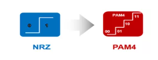
There are two technical directions for 200G optical modules, one is a 4x50G PAM4 network in the QSFP56 package; the other is an 8x25G NRZ network in the QSFP-DD package. In short, NRZ (non-return to zero) is a modulation technology with two voltage levels to represent logic 0 and logic 1. The voltage literally does not “return to zero”; logic 0 is a negative PAM4 that uses four voltage levels to represent four combinations of 2 bits logic: 11, 10, 01, and 00.
Compared with PAM4 technology, 200G NRZ (8X25G) has the advantages of low power consumption, low latency and easy deployment, so 200G NRZ can realize low-cost optical interconnection within data centers. Among the 200G NRZ optical modules, QSFP-DD LR4 and QSFP-DD ER4 are commonly available.
- 200G QSFP-DD LR4
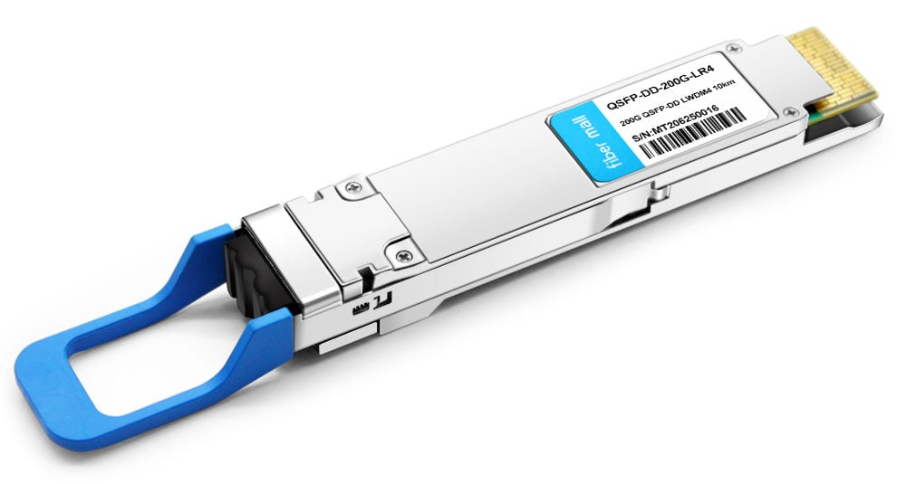
200G QSFP-DD LR4 converts the 8-channel of 25Gb/s or 4-channel of 50Gb/s electrical input data into LWDM optical signals. It contains a duplex LC connector for the optical interface and a 76-pin connector for the electrical interface. To minimize the optical dispersion in the long-haul system, single-mode fiber (SMF) has to be applied in this module. Host FEC is required to support up to 10km of fiber transmission.
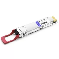
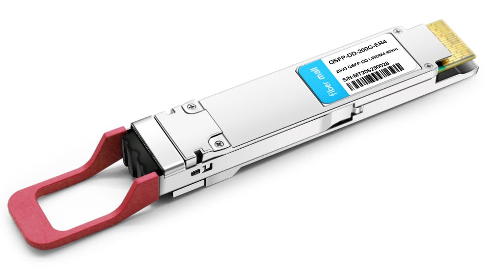
- 200G QSFP-DD ER4
The module incorporates 4 independent channels on LWDM4 1295.56, 1300.05, 1304.58, and 1309.14nm center wavelength, operating at 50G per channel. It contains a duplex LC connector for the optical interface and a 76-pin connector for the electrical interface. To minimize the optical dispersion in the long-haul system, single-mode fiber (SMF) has to be applied in this module. It can support up to 30km with 200G FEC and 40km with built-in PFEC.
Unlike NRZ, 4x50Gbps PAM4 technology for 200G transmission does not require the use of eight 25G channels for 200G transmission, which saves fiber cost and reduces link loss. Among the 200G PAM4 optical modules, QSFP56 SR4 and QSFP56 FR4 are the most commonly used.
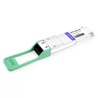
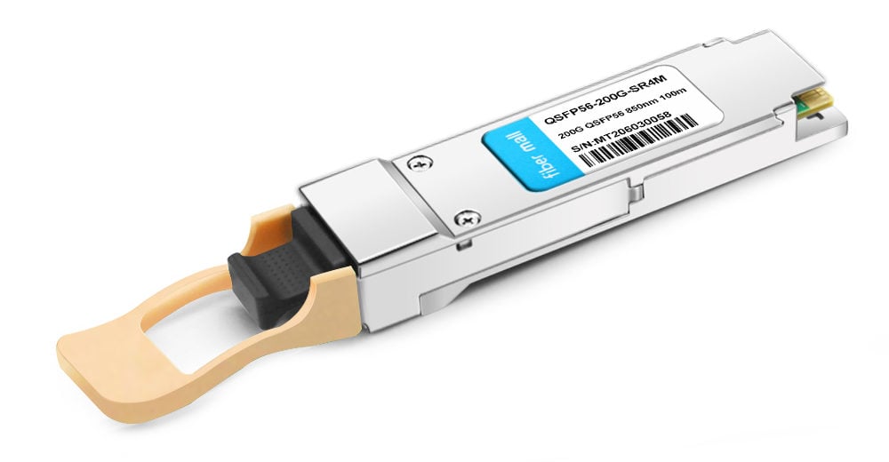
- 200G QSFP56 SR4
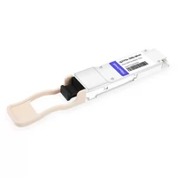
The QSFP56 SR4 full-duplex optical module offers 4 independent transmit and receive channels, each capable of 53.125Gb/s operation for an aggregate data rate of 200Gb/s on 70 meters of OM3 multi-mode fiber. An optical fiber cable with an MTP/MPO-12 APC connector can be plugged into the QSFP56 SR4 module receptacle. The central wavelengths of all 4 parallel lanes are 850nm. It contains an optical MPO-12 APC connector for the optical interface and a 38-pin connector for the electrical interface.
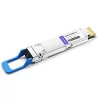
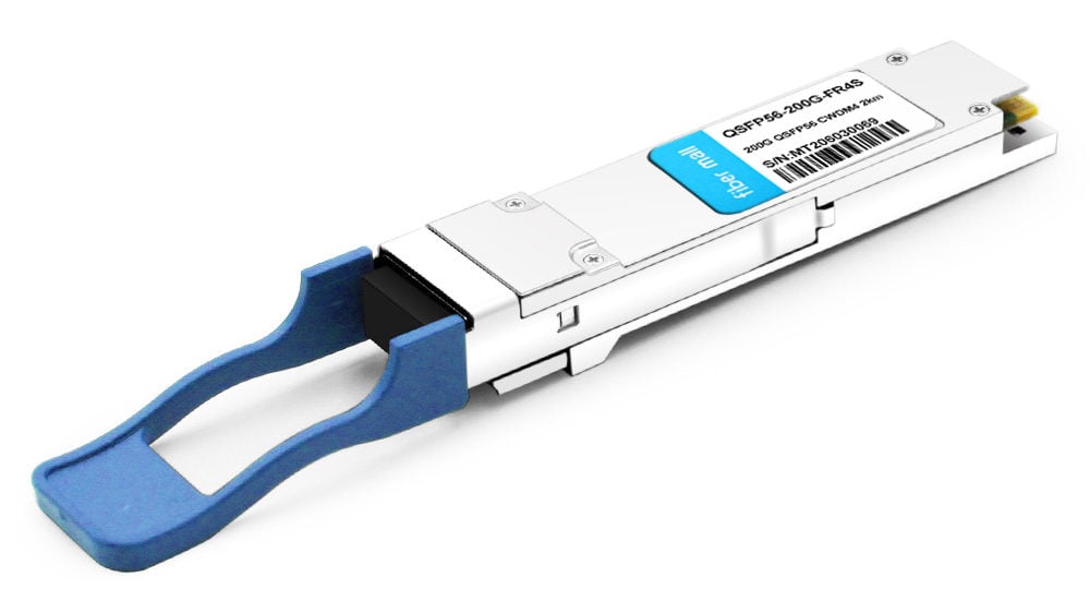
- 200G QSFP56 FR4
The 200G FR4 module converts the 4-channel 200Gb/s(PAM4) electrical input data into CWDM optical signals (light), by a driven 4-wavelength EMLs. The central wavelengths of the 4 CWDM channels are 1271, 1291, 1311, and 1331 nm as members of the CWDM wavelength grid defined in ITU-T G.694.2. It contains a duplex LC connector for the optical interface and a 38-pin connector for the electrical interface. It is designed for 2km optical communication applications.
3. 200G Ethernet Optical Transceiver Electrical Interface Solution
The 200G IEEE protocol standard was released later than the 400G standard, and the 200G standard was proposed in 2015 and approved in 2018. The IEEE802.3bs specification defines the electrical interface type of the 200G transceiver. What are the electrical interface solutions for the 200G Ethernet optical transceiver?
The electrical interface of the 200G optical transceiver currently adopts two signal schemes: NRZ and PAM4.
- 200G NRZ Solution

Schematic diagram of the PHY layer structure of the NRZ solution
The electrical interface name of the 200G NRZ solution is 200GAUI-8, with 8 channels and a single-channel rate at 26.5625Gbps. 200GAUI-8 is applied between PMA and PMA. The PMA part of the transceiver is a gearbox chip or a retimer chip, which can resample the signal to eliminate the influence of jitter and noise.
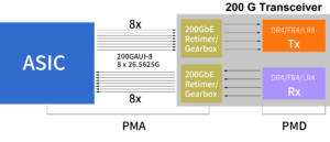
the 200GAUI-8 electrical interface
- 200G PAM4 Solution

Schematic diagram of the PHY layer structure of the PAM4 solution
The electrical interface of the 200G PAM4 solution is 200GAUI-4, the number of channels is reduced by half compared to the NRZ solution, and the single-channel rate is 26.5625GBd. Like 200GAUI-8, 200GAUI-4 is also used between PMA and PMA. The PMA part of the transceiver is a gearbox chip or a retimer chip, which can resample the signal to eliminate the influence of jitter and noise.
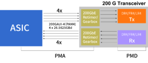
the 200GAUI-4 electrical interface
In addition to the type of electrical interface between PMA and PMA, the specification also defines the number of channels and signal rates for optical transmission at the single-mode PMD layer, so there will be many different types of interfaces between PMA and PMD.
The basic principle of single-mode 200G Ethernet is based on a variant of the 400G Ethernet specification, especially reflected in its use of 50 Gbps transmission in PAM4 and definition of 200Gbase-DR4, 200Gbase-FR4, and 200Gbase-LR4.
| PMD | |||||||
|---|---|---|---|---|---|---|---|
| Type | Channel | Modulation format | Baud rate | Bit Error Rate(BER) | Optical fiber | Channel insertion loss | Transmission distance |
| 200GBASE- DR4 | 4 | PAM4 | 26.5625GBD | BER<2.4E-4 | SMF | 3dB | 2m-500m |
| 200GBASE- FR4 | 4 | PAM4 | 26.5625GBD | BER<2.4E-4 | SMF | 4dB | 2m-2km |
| 200GBASE- LR4 | 4 | PAM4 | 26.5625GBD | BER<2.4E-4 | SMF | 6.3dB | 2km-10km |
Specifications of 200Gbase-DR4, 200Gbase-FR4, and 200Gbase-LR4 in the PMD
In order to match the transmission type of PMD, the signal type between PMA and PMD of 200Gbase-DR4 is also PAM4, which can be matched with 200GAUI-8 or 200GAUI-4 interfaces.
If the 200Gbase-DR4 is matched with a 200GAUI-4 electrical interface (PAM4), the PMA part inside the transceiver is a 4-way PAM4 Retimer.

200GAUI-4 electrical interface and a 4-way PAM4 Retimer for 200Gbase-DR4
If the 200Gbase-DR4 is matched with a 200GAUI-8 electrical interface (PAM4), then the PMA part inside the transceiver will be an 8-way NRZ to 4-way PAM4 Gearbox.

200GAUI-8 electrical interface and an 8-way NRZ to 4-way PAM4 Gearbox for 200Gbase-DR4
200Gbase-FR4 is similar to 200Gbase-LR4 and DR4 in that they all use a single-mode wavelength division multiplexing scheme, which combines four optical paths with different wavelengths into one and sends it out. Also in order to match the transmission type of PMD, the signal type between PMA and PMD is PAM4, which can be matched with 200GAUI-8 or 200GAUI-4 interfaces. If the 200Gbase-FR4/DR4 is compared with a 200GAUI-4 electrical interface, the PMA part inside the transceiver will be a 4-way PAM4 Retimer.

200GAUI-4 electrical interface and 4-way PAM4 Retimer for 200Gbase-FR4/DR4
If it is matched with a 200GAUI-8 electrical interface (PAM4), the PMA part inside the transceiver will be an 8-way NRZ to 4-way PAM4 Gearbox.

200GAUI-8 electrical interface and 8-way NRZ to 4-way PAM4 Gearbox for 200Gbase FR4/ DR4
The 200G single-mode PAM4 solution can make 2m to 10km transmission happen. If it uses a 200GAUI-4 electrical interface, a 4-channel PAM4 Retimer will be used inside the transceiver; if it adopts the 200GAUI-8 electrical interface (PAM4), and the PMA part inside the transceiver will use an 8-way NRZ to 4-way PAM4 Gearbox, which is optional to manufacturers. FiberMall200G QSFP56 DR4/FR4 optical transceivers all use a 200GAUI-4 electrical interface.
4. 200G optical transceiver: new choice for data center
In 2020, the large-scale application of online services promoted by COVID-19 brought new growth opportunities to the data center market and accelerated the upgrading and updating of data center technology. New applications such as 4K HD video, live streaming, and VR have promoted the rapid growth of network traffic and the demand for emerging applications such as cloud computing, IAAs services, and Big Data, which puts forward higher requirements for internal data transmission in the data center. Therefore, higher bandwidth transmission such as 200G or 400G is being realized in the data center. IEEE (Institute of Electrical and Electronics Engineers) standardized 200G and 400G, especially for DCN(Data Communication Network). 400G was approved by the IEEE 802.3bs Ethernet standard as early as 2017 and was originally proposed in 2013. On the other hand, 200G was approved in 2018, and the initial proposal appeared in 2015. 200G and 400G have almost the same standards and requirements, but the 400G optical transceiver is not widely used in the market. And for 200G optical modules, there are not many manufacturers who can provide them either, FiberMall is an exception. For the data center, upgrading from 100G to 200G is the best solution. The technology of 200G is more mature than 400G. Due to the competition between OEM (Original Equipment Manufacturer) and third-party module manufacturers, it also provides more options for 200G optical modules and reduces its purchase cost. Therefore, a data center with a tight budget can postpone the more expensive 400G upgrade to later and adopt the intermediate scheme of 200G first. FiberMall can provide you with high-quality 200G optical modules, including full series of 200G QSFP56 transceivers, QSFP56 AOC, 200G QSFP-DD transceivers, and QSFP-DD AOC.
Related Products:
-
 QSFP56-200G-FR4S 200G QSFP56 FR4 PAM4 CWDM4 2km LC SMF FEC Optical Transceiver Module
$650.00
QSFP56-200G-FR4S 200G QSFP56 FR4 PAM4 CWDM4 2km LC SMF FEC Optical Transceiver Module
$650.00
-
QSFP56-200G-SR4M 200G QSFP56 SR4 PAM4 850nm 100m MTP/MPO APC OM3 FEC Optical Transceiver Module
$139.00
-
QSFP-DD-200G-LR4 200G QSFP-DD LR4 PAM4 LWDM4 10km LC SMF FEC Optical Transceiver Module
$1000.00
-
QSFP-DD-200G-ER4 200G QSFP-DD ER4 PAM4 LWDM4 40km LC SMF FEC Optical Transceiver Module
$1500.00
-
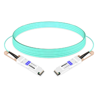
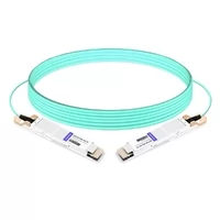
QSFP56-200G-AOC-1M 1m (3ft) 200G QSFP56 to QSFP56 Active Optical Cable
$330.00
-
QSFP-DD-200G-AOC-1M 1m (3ft) 200G QSFP-DD to QSFP-DD Active Optical Cable
$560.00
-
NVIDIA(Mellanox) MMA1T00-VS Compatible 200G Ethernet QSFP56 SR4 PAM4 850nm 100m MTP/MPO APC OM3 FEC Optical Transceiver Module
$139.00
-
NVIDIA(Mellanox) MFS1S00-H003E Compatible 3m (10ft) 200G HDR QSFP56 to QSFP56 Active Optical Cable
$350.00