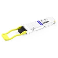
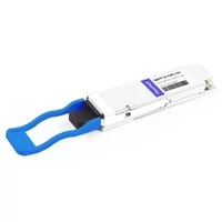
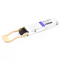
Ask five network engineers whether they should deploy QSFP112 or QSFP-DD for a 400G network, and you may get five different answers. Both form factors can support 400G, both are widely available, and both have legitimate advantages depending on the platform.
The right choice depends on your switch or NIC hardware, fiber infrastructure, port architecture, thermal budget, and future bandwidth requirements—not simply on which form factor is newer.
This guide explains the factors that actually matter: QSFP112 electrical architecture, module types from VR4 and SR4 to LR4, 200G and 100G breakout options, power and thermal considerations, current market pricing, and vendor-specific compatibility.
One issue appears repeatedly in real deployments: a QSFP112 module physically fits into a QSFP-style cage, so the installer assumes that it will work. The link then fails to initialize or operates incorrectly.
The problem may be the host electrical interface, FEC configuration, management-interface implementation, firmware support, or an unsupported module profile.
Physical fit and electrical compatibility are not the same thing. That distinction is fundamental to deploying QSFP112 correctly.
What Is QSFP112?
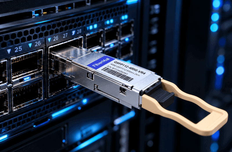
QSFP112 is a four-lane high-speed pluggable form factor commonly used for 400G Ethernet and InfiniBand connectivity. The “112” designation refers to the 112G-class SerDes generation.
For 400G operation, the host electrical interface typically uses four PAM4 lanes operating at approximately 106.25 Gb/s per lane, producing an aggregate signaling rate of about 425 Gb/s. The corresponding four-lane host interface is 400GAUI-4, defined by IEEE 802.3ck.
In practical terms:
- QSFP28: typically 4 × ~25 Gb/s NRZ electrical lanes for 100G
- QSFP56: typically 4 × ~50 Gb/s PAM4 electrical lanes for 200G
- QSFP112: typically 4 × ~100 Gb/s PAM4 electrical lanes for 400G
QSFP112 retains the familiar QSFP-class front-panel width and height, but module-body and pull-tab lengths can vary by implementation. Therefore, it is better to think of QSFP112 as part of the QSFP mechanical family rather than assume that every QSFP-generation module has identical dimensions.
Three compatibility factors matter most.
1. Host Electrical Interface
The host must support the electrical lane rate required by the QSFP112 module.
A legacy QSFP28 port designed for approximately 25 Gb/s NRZ per lane cannot operate a 400G QSFP112 module that requires approximately 100 Gb/s PAM4 per lane, even if the module can be physically inserted.
Likewise, support for lower-speed modules in a QSFP112 host depends on the switch or NIC implementation. Some multi-rate ports can operate QSFP56 or QSFP28 modules, while others have more limited combinations.
Always check the exact hardware compatibility matrix.
2. Management Interface and Firmware
QSFP112 modules may use different revisions of the Common Management Interface Specification (CMIS), depending on the module vendor and host platform.
There is no universal rule that every QSFP112 deployment requires CMIS 5.2. Modules using CMIS 4.x, 5.0, 5.1, or 5.2 may all exist in the market.
What matters is whether the module’s management implementation is compatible with the host firmware.
Newer CMIS revisions can add or expand diagnostic and management functions, but a higher revision number does not automatically make a module compatible with every switch or NIC.
Before deployment, confirm:
- Module CMIS revision
- Host-supported CMIS revision
- Required module firmware
- Supported diagnostics and VDM functions
- Vendor qualification status
3. FEC and Port Mode
400G PAM4 links depend heavily on forward error correction.
The correct FEC behavior is determined by the Ethernet or InfiniBand PHY and the specific port mode. Both ends must be configured for compatible signaling and FEC behavior.
Incorrect FEC settings can result in a port that fails to train, repeatedly flaps, or accumulates excessive pre-FEC errors.
Do not treat FEC as an optional tuning parameter. It is part of the link architecture.
QSFP112 vs QSFP-DD: The 400G Decision
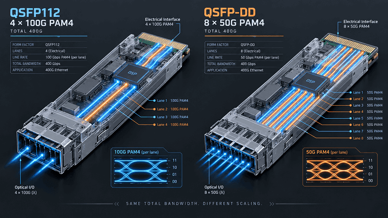
For 400G deployments, QSFP112 and QSFP-DD can serve similar applications, but their electrical architectures are fundamentally different.
QSFP112 uses four high-speed electrical lanes.
Traditional 400G QSFP-DD implementations commonly use eight lower-rate electrical lanes, such as 8 × 50G-class PAM4, and may use an internal gearbox when the optical interface operates as four 100G-class lanes.
Newer QSFP-DD800 implementations can use eight 100G-class electrical lanes to support 800G.
That difference has important consequences.
| Feature | QSFP112 | QSFP-DD |
| Electrical lane count | 4 | 8 |
| Typical 400G host architecture | 4 × ~100G PAM4 | 8 × ~50G PAM4 |
| 800G path | Not within standard four-lane QSFP112 | Supported by QSFP-DD800 |
| Front-panel family | QSFP | Double-density QSFP |
| Legacy QSFP module support | Host-dependent | Many QSFP-DD cages can accept selected QSFP modules |
| Typical 400G use | NICs, HCAs, DPUs, selected platforms | High-density Ethernet switches |
| Power | Depends on optical design and DSP | Depends on optical design and DSP |
The 800G Difference
QSFP112 itself is a four-lane form factor designed around the 100G-per-lane generation, making it a natural fit for 400G.
If the same physical port must later support 800G, an eight-lane interface such as QSFP-DD800 or OSFP is generally the more appropriate architecture.
This does not make QSFP112 obsolete. It means the form factor is optimized for a different port architecture.
Do Not Assume a Fixed Power Advantage
QSFP112 is often described as lower-power than QSFP-DD, but the comparison should not be made from form factor alone.
Power consumption is heavily influenced by:
- Optical reach
- Laser technology
- DSP architecture
- Gearbox requirements
- Optical lane count
- Thermal design
A QSFP112 SR4 or DR4 module may consume around 8–10 W, while some comparable QSFP-DD implementations may consume more. However, another QSFP-DD design may have similar power consumption.
Compare the actual maximum power specification of the modules being evaluated rather than assuming a fixed 2 W advantage.
Mechanical Backward Compatibility Is Asymmetric
A QSFP-DD cage is designed with additional electrical contacts while retaining mechanical compatibility with selected earlier four-lane QSFP modules.
Therefore, many QSFP-DD host ports can accept QSFP28 or QSFP56 modules, subject to platform support.
The reverse is not true: a QSFP-DD module cannot be inserted into a conventional four-lane QSFP cage.
Electrical operation is still host-dependent even when the module physically fits.
QSFP112 Module Types and Specifications
QSFP112 modules are available with different optical PMDs, fiber types, connectors, and reaches.
The correct choice should be made before designing the fiber plant.
400G VR4
VR4 is intended for very short multimode links.
Typical characteristics include:
- 850 nm
- OM3/OM4 multimode fiber
- MPO-12/APC
- Up to approximately 50 m on OM4
- Four parallel 100G-class PAM4 optical lanes
VR4 is particularly attractive for short AI and HPC links where cable lengths are tightly controlled.
400G SR4
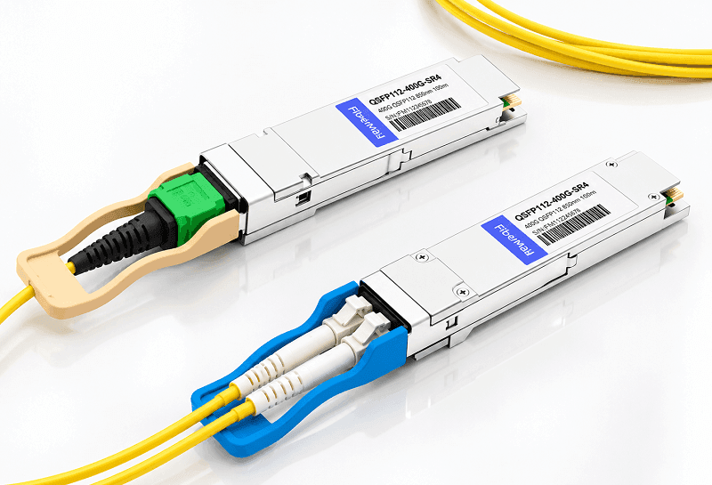
QSFP112 SR4 implementations use four parallel multimode optical lanes and typically use MPO connectivity.
Depending on the exact standard and vendor implementation, advertised reach can vary. Some products are optimized for approximately 50 m, while other vendor implementations specify up to 100 m on OM4.
For this reason, do not select an SR4 module based only on the “SR4” name. Verify the exact reach, fiber grade, optical connector, and interoperability specification.
400G DR4
DR4 is one of the most important QSFP112 single-mode interfaces.
Typical characteristics are:
- Four parallel single-mode optical lanes
- Approximately 1310 nm
- MPO-12/APC
- Up to 500 m over single-mode fiber
- Support for optical breakout to compatible 100G DR1 or 200G DR2 interfaces
DR4 is widely used for data-center leaf-spine connectivity and AI fabrics because its parallel optical architecture maps naturally to 100G-per-lane networks.
400G FR4
FR4 combines four optical wavelengths onto a duplex single-mode fiber pair.
Typical characteristics include:
- Duplex LC
- Single-mode fiber
- Four CWDM wavelengths
- Up to 2 km
- 400G over one fiber pair
FR4 is attractive where operators want to avoid parallel MPO cabling or need longer links between rows, buildings, or data-center zones.
400G LR4
LR4 requires more careful terminology.
IEEE defines 400GBASE-LR4-6, which supports approximately 6 km.
The industry also offers 400G-LR4-10 products based on specifications such as the 100G Lambda MSA, providing up to approximately 10 km.
Both may be marketed informally as “400G LR4,” so check the exact compliance statement before specifying the module.
For long single-mode links, verify:
- LR4-6 versus LR4-10
- Link budget
- Fiber attenuation
- Connector loss
- FEC requirements
- Host compatibility
Quick Comparison
| Module | Fiber | Typical Reach | Connector | Typical Application |
| VR4 | OM3/OM4 MMF | Up to 50 m | MPO-12 | Very short AI/HPC links |
| SR4 | OM4 MMF | ~50–100 m, implementation-dependent | MPO | Short data-center links |
| DR4 | SMF | 500 m | MPO-12 | Leaf-spine, AI fabrics |
| FR4 | SMF | 2 km | Duplex LC | Campus/DC interconnect |
| LR4-6 | SMF | 6 km | Duplex LC | Extended DCI |
| LR4-10 | SMF | 10 km | Duplex LC | Metro/longer DCI |
MPO polarity, connector polish, and fiber type matter just as much as nominal reach. An MPO cable that physically connects two modules can still be incompatible because of polarity or APC/UPC requirements.
QSFP112 for 200G and 100G Networks
One of QSFP112’s most useful features is its ability to participate in lower-speed breakout architectures.
However, breakout needs to be understood at the lane level, not simply by dividing 400G mathematically.
400G to 2×200G
A four-lane 400G interface can be divided into two logical 200G interfaces when the host ASIC supports the required port mode.
Each 200G connection can use two 100G-class PAM4 lanes.
This architecture is particularly common in modern AI networks using 100G-PAM4 signaling.
Depending on the platform, the breakout may be implemented with:
- Passive copper splitter cables
- Active copper cables
- AOCs
- Parallel optical modules and fiber splitters
The exact far-end connector depends on the NIC or HCA architecture.
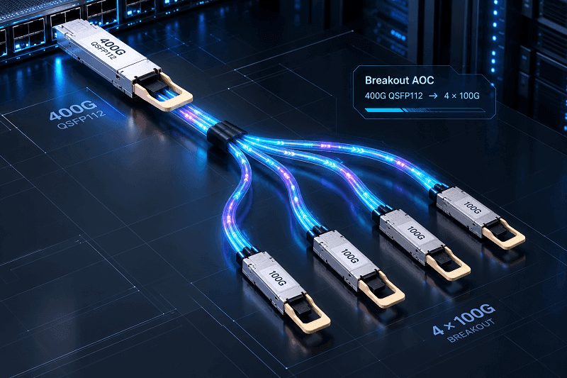
400G to 4×100G
A four-lane 400G optical interface such as DR4 or VR4 can also support four independent 100G optical lanes when the host and optics support breakout mode.
For example:
- 400G DR4 can connect to four compatible 100G DR1 endpoints.
- 400G VR4 can connect to four compatible 100G VR1 endpoints.
This is fundamentally different from saying that any QSFP112 port can passively break out into four legacy QSFP28 ports.
A traditional 100G QSFP28 host commonly uses four ~25G NRZ electrical lanes, while a QSFP112 host uses ~100G PAM4 electrical lanes.
A passive cable cannot perform that electrical rate conversion.
If the far-end transceiver or cable contains the necessary gearbox or signal conversion, interoperability may be possible. Without it, the two electrical architectures are not equivalent.
Check ASIC Breakout Restrictions
Not every switch or NIC supports every combination.
Possible restrictions include:
- Only certain ports support breakout
- Ports operate in groups
- Changing one port mode affects adjacent ports
- Different FEC settings are required
- Breakout is supported only with qualified cables
- Ethernet and InfiniBand modes support different combinations
Always verify the port-mode table for the exact hardware SKU before ordering breakout cables.
QSFP112 Cabling Options
The transceiver is only half the link. The cable plant determines reliability, cost, and how painful deployment gets.
Passive DAC is the cheapest option at very short reach. QSFP112 passive DACs run from 0.5 to 2 meters. Wire gauge matters here. Thinner 30AWG cable is more flexible but loses signal faster. 26AWG holds distance better and routes badly in dense racks. For 1-meter intra-rack links, 28AWG is the sweet spot.
Active DAC and ACC extend passive reach to 2-3 meters by adding signal conditioning inside the assembly. They cost more than passive copper and less than optics. Adjacent-rack links are the usual fit.
AOC replaces copper with fiber and active optical engines in the connector heads. QSFP112 AOCs cover 1 to 100 meters. They are lighter and more flexible than DACs, and they draw slightly more power, usually 1-2W per end. Past 3 meters, AOC is normally the better call.
Breakout DAC and AOC handle the 2×200G and 4×100G splits from the previous section. A 400G QSFP112 to 2×200G breakout AOC connects two GPU servers into one spine port without separate modules. The far-end connector matches the target form factor, typically QSFP56 at 200G or QSFP28 at 100G.
Fiber requirements follow the module. SR4 and VR4 need OM4 multimode with MPO-12. DR4, FR4, and LR4 need OS2 single-mode, with duplex LC for the long-reach variants.
Plan the fiber plant before committing to a module type. Re-cabling a live data hall costs far more than the optics.
Power and Thermal at Scale
Per-module power ratings undersell the difference. At scale, QSFP112’s 8-10W per module becomes a real line item in both electrical and cooling budgets.
A 32-port 400G leaf switch fully loaded with QSFP112 modules draws 256-320W for optics alone. The same switch loaded with QSFP-DD draws 320-384W. That is 64W per switch, multiplied across a pod.
A 128-port spine at full fill separates the two more sharply: 1,024-1,280W with QSFP112 against 1,280-1,536W with QSFP-DD.
| Scale | QSFP112 load | QSFP-DD load | Savings |
| 32-port switch | 256-320W | 320-384W | 64W+ |
| 128-port leaf | 1,024-1,280W | 1,280-1,536W | 256W+ |
| 1,000-port cluster | 8,000-10,000W | 10,000-12,000W | 2,000W+ |
Run those numbers against a 2,000-port AI training cluster and the delta lands near 4 kW of optical power. At a PUE of 1.35, that becomes roughly 5.4 kW of facility load, or about $4,700 a year at typical US commercial rates. Meaningful, though not transformative on its own.
The cooling side matters more than the electricity bill. Transceiver reliability data generally shows a 10-15% improvement in MTBF for every 5°C drop in operating temperature. If your facility is thermally constrained, QSFP112’s lower draw buys GPU headroom without adding cooling units.
Real-World Pricing (2026)
QSFP112 pricing has declined as 400G AI and data-center deployments have expanded, but pricing varies dramatically depending on:
- Optical PMD
- Reach
- DSP and laser technology
- OEM coding
- Vendor qualification
- Warranty
- Order volume
- TAA requirements
- Distribution channel
Public online listings in 2026 show that third-party QSFP112 modules can be significantly less expensive than traditional OEM-branded optics.
As a general planning reference, short-reach third-party VR4/SR4 modules can appear in the mid-hundreds of dollars, while DR4 and FR4 products typically increase with optical complexity and reach.
Distributor, TAA-compliant, and OEM-coded versions can cost two to several times more than aggressive third-party online pricing.
Because prices move quickly, avoid publishing a fixed “market price” without a date.
A better procurement table is:
| Product Type | Relative Cost | Main Cost Drivers |
| 400G VR4/SR4 | Low | VCSEL, MMF, short reach |
| 400G DR4 | Low–Medium | Parallel SMF optics |
| 400G FR4 | Medium | CWDM optics, mux/demux |
| 400G LR4 | Medium–High | EML/CWDM, longer optical budget |
| OEM-coded module | High | Qualification, support, vendor margin |
NIC and HCA pricing should be evaluated separately.
Adapter pricing varies widely by PCIe generation, port count, Ethernet/InfiniBand capability, crypto features, OEM channel, and supply conditions. Comparing optics and adapters as a single fixed “cost per port” can therefore produce misleading results.
For large deployments, request project pricing based on the exact:
- Switch model
- NIC/HCA model
- Cable length
- Optical reach
- Port mode
- Required compatibility coding
- Quantity
Volume purchasing can materially change the economics.
NVIDIA Ecosystem and InfiniBand NDR
QSFP112 has become especially important because of NVIDIA’s 100G-PAM4 networking architecture.
However, NVIDIA does not use one connector type across every 400G product.
Understanding the switch side and adapter side separately prevents many ordering mistakes.
Quantum-2 and Spectrum-4 Switches
NVIDIA Quantum-2 NDR InfiniBand switches and Spectrum-4 SN5600-class Ethernet switches use twin-port OSFP cages in major 100G-PAM4 implementations.
A twin-port OSFP cage can carry two independent 400G ports, producing up to 800G of aggregate connectivity through one physical cage.
Therefore, the switch side of an NVIDIA NDR deployment is commonly OSFP rather than QSFP112.
QSFP112 is widely used on the adapter or DPU side.
This leads to common cabling patterns such as:
- Twin-port OSFP switch → 2×400G QSFP112
- Twin-port OSFP switch → 4×200G QSFP112
- OSFP switch → OSFP adapter
- Optical OSFP → parallel fiber → QSFP112 optical endpoint
ConnectX-7: Check the Exact SKU
ConnectX-7 is available in multiple connector and speed configurations.
This is one of the biggest sources of procurement mistakes.
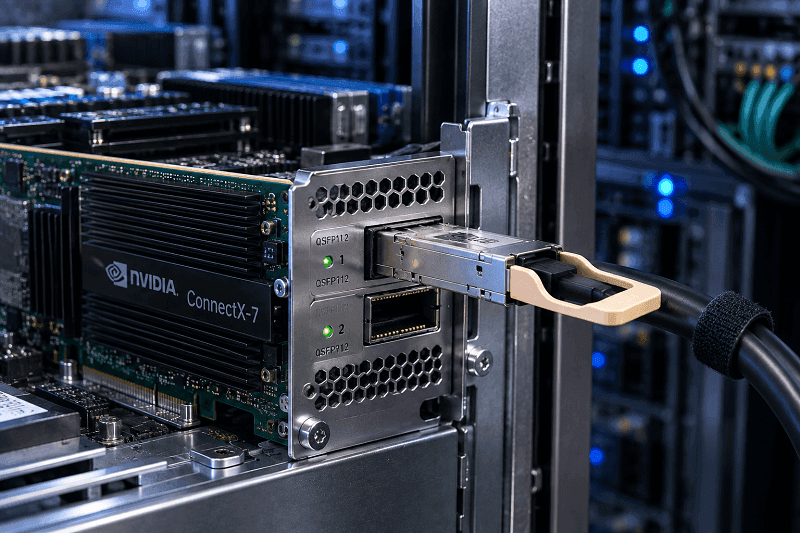
For example, some ConnectX-7 cards use dual-port QSFP112 interfaces operating at up to 200 Gb/s per port.
The MCX755106AS-HEAT family is an example of this architecture, supporting 200GbE or NDR200 per port.
Other ConnectX-7 models support a single 400G QSFP112 port, while additional variants use single-port OSFP for 400G/NDR connectivity.
Therefore:
QSFP112 connector ≠ automatically 400G port.
The adapter SKU determines the supported rate.
ConnectX-8
ConnectX-8 extends NVIDIA’s networking architecture further.
The C8240 uses dual QSFP112 ports and supports up to 400GbE or 400 Gb/s InfiniBand per port.
By contrast, the C8180 uses a single OSFP cage and supports 800 Gb/s XDR InfiniBand or 2×400GbE.
Again, the connector and product SKU must be considered together.
BlueField
BlueField-3 DPUs are another important QSFP112 deployment area.
In NVIDIA’s 100G-PAM4 ecosystem, QSFP112 is commonly used on the DPU side while the fabric switch may use twin-port OSFP.
This asymmetric connector arrangement is normal and is handled with qualified cables or optical solutions.
NDR and NDR200
NDR signaling is based on 100G-class PAM4 electrical lanes.
At the logical link level:
- NDR: 400 Gb/s using four 100G-class lanes
- NDR200: 200 Gb/s using two 100G-class lanes
That architecture explains why a four-lane 400G fabric interface can be divided into two 200G connections.
It also explains why NDR200 should not be confused with older 200G HDR signaling, which uses a different electrical lane architecture.
Vendor Compatibility Notes
Switch vendor support varies widely. Check this list before you order.
Cisco supports QSFP112 on selected Nexus 9000 platforms with the right line cards. Not every N9K does 400G, and fewer still do QSFP112 specifically. Cisco also expects its own optics for TAC coverage, though third-party MSA modules usually link up.
Arista has been the most aggressive adopter. The 7060X5 and 7800R3 series support QSFP112 natively, and Arista’s multi-rate ports negotiate down to 200G or 100G, which simplifies mixed-speed environments. EOS handles CMIS 5.2 diagnostics well.
NVIDIA/Mellanox is the native ecosystem. Spectrum-4 and Quantum-2 are built around the OSFP side of the QSFP112/OSFP pairing described above, so matching NVIDIA NICs to NVIDIA switches removes most guesswork.
Juniper supports QSFP112 on the PTX10008 and selected QFX platforms. The implementation is solid but the supported platform list is narrower than Arista’s. Verify your line card and Junos version first.
Third-party MSA modules work in most platforms when CMIS is implemented correctly. The failure mode we see most often is incomplete digital diagnostic monitoring. A module links up but reports temperature, voltage, or Rx power inaccurately, which breaks monitoring scripts and fires false alarms in your NMS.
When to Choose QSFP112
The decision compresses into two short lists.
Choose QSFP112 when:
- You are building AI/ML clusters on NVIDIA ConnectX-7 or ConnectX-8 adapters
- Power and thermal budgets are tight
- You are deploying greenfield 400G infrastructure
- Rack density matters more than an 800G upgrade path
- Your longest spans are under 10 km, which QSFP112 covers
Avoid QSFP112 when:
- You need 800G on the same hardware
- You have extensive QSFP28 or QSFP56 gear you want to interoperate with electrically
- Maximum backward compatibility is the top priority
- Your switch platform only offers QSFP-DD cages
The power advantage is real. So is the missing 800G path. If you expect to need 800G within three years, QSFP-DD or OSFP is the safer long-term bet.
Some teams split the difference, running QSFP112 on server-facing ports where NVIDIA adapters dominate and QSFP-DD on spine ports where bandwidth growth matters more. It isn’t elegant, but it works.
Conclusion
QSFP112 is one of the most important 400G form factors in modern AI, HPC, Ethernet, and InfiniBand networks.
Its four-lane 100G-PAM4 electrical architecture provides an efficient path to 400G in a compact QSFP-class form factor, particularly for NICs, HCAs, and DPUs.
But QSFP112 should not be treated as simply “a faster QSFP28.”
Before placing an order, make five checks:
- Confirm the host supports the required QSFP112 electrical interface and port speed.
- Verify the module’s management interface and firmware compatibility with the host.
- Match the optical PMD, fiber type, connector, and reach to the existing cabling infrastructure.
- If breakout is required, confirm the lane architecture on both ends—not just the connector type.
- Calculate power and thermal load using actual module specifications rather than generic form-factor assumptions.
QSFP112 does not provide an 800G path within the same four-lane interface, and it cannot automatically interoperate with legacy QSFP28 or QSFP56 electrical architectures.
What it does provide is a compact and efficient 400G platform built around 100G-per-lane signaling.
For greenfield 400G AI fabrics, NVIDIA adapter connectivity, and other 100G-PAM4 applications, that makes QSFP112 a highly practical option—provided the optics, cables, host hardware, firmware, and port modes are validated as a complete system.
Related Products:
-
 QSFP112-400G-SR4 400G QSFP112 SR4 PAM4 850nm 100m MTP/MPO-12 OM3 FEC Optical Transceiver Module
$400.00
QSFP112-400G-SR4 400G QSFP112 SR4 PAM4 850nm 100m MTP/MPO-12 OM3 FEC Optical Transceiver Module
$400.00
-
QSFP112-400G-DR4 400G QSFP112 DR4 PAM4 1310nm 500m MTP/MPO-12 with KP4 FEC Optical Transceiver Module
$500.00
-
QSFP112-400G-FR1 4x100G QSFP112 FR1 PAM4 1310nm 2km MTP/MPO-12 SMF FEC Optical Transceiver Module
$800.00
-
QSFP112-400G-FR4 400G QSFP112 FR4 PAM4 CWDM 2km Duplex LC SMF FEC Optical Transceiver Module
$600.00
-
QSFP112-400G-LR4 400G QSFP112 LR4 PAM4 CWDM 10km Duplex LC SMF FEC Optical Transceiver Module
$1000.00
-
FiberMall QSFP112-400G-VR4 Compatible 400G QSFP112 VR4 PAM4 850nm 50m MTP/MPO-12 OM4 FEC Optical Transceiver Module
$385.00