A metro fiber route between two data centers can reach its capacity limit faster than expected. When it does, the immediate response may be to deploy additional fiber. However, installing new fiber infrastructure can take months or even years and may cost more than the networking equipment at both ends. Engineers therefore turn to another approach: increasing the capacity of existing fiber infrastructure.
That approach is dense wavelength division multiplexing, or DWDM. It combines dozens of independent optical channels onto a single fiber, with each channel transmitted at a distinct wavelength. DWDM has supported telecommunications backbones for decades and is increasingly used in data center interconnect (DCI), metro networks, and high-capacity infrastructure supporting AI workloads.
This guide provides a complete overview of DWDM technology. You’ll learn how DWDM works, how it differs from CWDM, how the ITU-T grid defines optical channels, which components make up a DWDM system, and how to design a reliable optical network with appropriate protection mechanisms. Need help selecting the right hardware? Contact FiberMall’s optical transport engineers before choosing your modules and equipment.
What Is DWDM?
Dense wavelength division multiplexing (DWDM) is an optical communication technology that carries multiple independent data streams over a single optical fiber by assigning each stream a different wavelength of light. DWDM channels are closely spaced, commonly at 50 GHz or 100 GHz intervals, corresponding to approximately 0.4 nm or 0.8 nm near 1550 nm. Higher-density systems may use 25 GHz spacing or flexible-grid channel allocations.
Picture a highway. A conventional single-wavelength optical link uses one lane, while DWDM creates dozens of lanes on the same fiber. Each wavelength carries an independent optical signal, allowing multiple services to share the available fiber capacity. Proper wavelength spacing, optical filtering, and power management minimize interference between adjacent channels.
The concept is not new. Early wavelength division multiplexing systems emerged in the 1980s, commonly combining optical signals around 1310 nm and 1550 nm. By the mid-1990s, advances in narrowband filters, wavelength-stabilized lasers, and optical amplification made DWDM practical for large-scale telecommunications networks.
Why DWDM Exists
Installing fiber infrastructure is expensive, but an existing fiber can support substantially more traffic than a single optical channel can carry. DWDM addresses this capacity gap by transmitting multiple wavelengths simultaneously, allowing operators to increase bandwidth without deploying additional fiber.
This is the fundamental advantage of DWDM. When traffic demand exceeds the capacity of an existing fiber route, network operators can either install additional fiber or increase the number and capacity of optical channels. Where suitable fiber and optical infrastructure already exist, adding DWDM capacity may require significantly less time and investment than constructing a new fiber route.
How DWDM Works
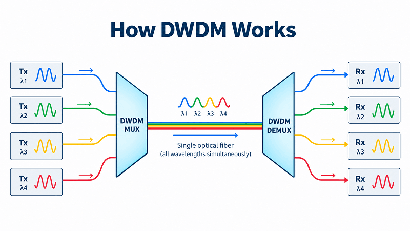
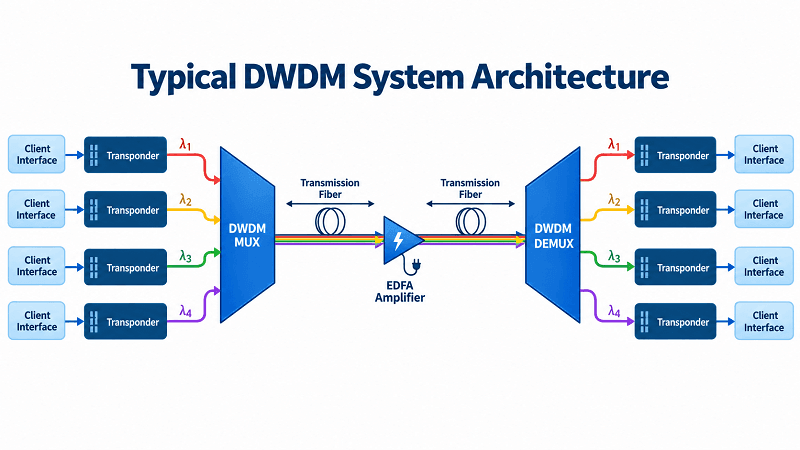
Three principles explain how DWDM operates: multiple wavelengths carry independent optical channels, multiplexers combine and separate those channels, and optical amplifiers compensate for transmission losses over longer distances.
Wavelength as an Independent Channel
Each DWDM channel operates at a designated optical carrier frequency. Channels remain distinguishable because they occupy different frequency slots within the optical spectrum. Proper channel spacing and filtering allow multiple signals to propagate through the same fiber while keeping inter-channel interference within acceptable limits.
One important advantage of DWDM is its ability to transport different client protocols and data rates. At the optical multiplexing layer, DWDM can carry Ethernet, Fibre Channel, SONET/SDH, and other services, provided that the associated optical interfaces and transmission characteristics are compatible with the system.
For example, a DWDM system can transport a 10G service on one wavelength and a 100G service on another. The signals share the same physical fiber but operate as separate optical channels. This flexibility allows operators to upgrade individual services without replacing the entire optical transport infrastructure.
Multiplexing and Demultiplexing
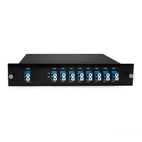
A multiplexer (MUX) combines multiple optical wavelengths into a single output fiber. At the receiving end, a demultiplexer (DEMUX) separates the combined signal into individual wavelength channels.
Passive DWDM MUX/DEMUX devices perform these functions without requiring electrical power for the wavelength multiplexing and demultiplexing process. However, complete DWDM systems may also include powered components such as amplifiers, transponders, optical switches, and monitoring equipment.
Common MUX/DEMUX technologies include thin-film filters (TFF), arrayed waveguide gratings (AWG), and other wavelength-selective optical filtering structures. These components provide channel separation and isolation to limit optical crosstalk.
Many passive MUX/DEMUX devices are reciprocal, meaning the same optical filtering structure can operate in either direction, depending on how the ports are connected and how the system is designed.
Amplification and Reach
One of the technologies that made long-distance DWDM practical was the erbium-doped fiber amplifier (EDFA). An EDFA amplifies multiple optical channels simultaneously without converting each signal into an electrical signal and back into light.
Before optical amplifiers became widely available, long-distance optical systems relied more heavily on electrical regeneration. As DWDM channel counts increased, regenerating every wavelength individually would have added substantial equipment cost and complexity.
An EDFA uses a section of optical fiber doped with erbium ions, typically pumped by a 980 nm or 1480 nm laser. It can provide optical gain across the C-band, approximately 1530–1565 nm, with the exact gain range and spectral characteristics depending on the amplifier design.
Typical EDFA gain may be around 15–25 dB or higher, depending on the model, input power, and operating configuration. By combining optical amplifiers with appropriate transceivers and system engineering, DWDM networks can support transmission over hundreds or even thousands of kilometers without requiring electrical regeneration at every amplification site.
However, optical amplification restores signal power rather than the original optical signal-to-noise ratio (OSNR). Amplifier noise and other transmission impairments accumulate along the link and must be considered in long-distance system design.
DWDM vs CWDM vs WDM
CWDM and DWDM are two widely deployed forms of wavelength division multiplexing. WDM is the broader technology category, while CWDM and DWDM differ primarily in channel spacing, wavelength stability requirements, capacity, and typical deployment scenarios.
| Parameter | CWDM | DWDM |
| Channel spacing | 20 nm | Commonly 50 or 100 GHz (approximately 0.4–0.8 nm near 1550 nm) |
| Channels per fiber | Commonly 8–18 | Commonly 40–96; 160+ with suitable spectrum and channel plans |
| Wavelength range | 1271–1611 nm nominal center wavelengths | Primarily C-band (approximately 1530–1565 nm); L-band also supported |
| Reach | Commonly up to 80 km, depending on optics and link loss | From short-reach links to hundreds or thousands of kilometers with appropriate amplification |
| Amplification | Limited with conventional wideband CWDM systems | EDFA amplification widely used in C-band and L-band systems |
| Cost | Generally lower for smaller-capacity systems | Generally higher equipment complexity, but greater spectral capacity |
| Typical use | Access, enterprise, and metro networks | Metro, long-haul, backbone, and DCI networks |
The trade-off is relatively straightforward. DWDM supports much tighter wavelength spacing and greater spectral efficiency but requires precise wavelength control and more demanding optical filtering. Traditional DWDM transmitters commonly use temperature-controlled lasers to maintain frequency stability.
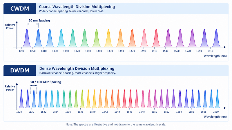
CWDM uses significantly wider wavelength spacing, allowing many CWDM transceivers to operate with uncooled lasers and lower component costs.
For networks that require only a few optical channels over relatively short distances, CWDM is often the more economical choice. For higher channel counts, greater spectral capacity, or long-distance amplified transmission, DWDM generally offers greater flexibility.
Another practical difference is optical amplification. Conventional EDFAs provide gain over a relatively narrow spectral region compared with the full CWDM wavelength range. As a result, standard EDFAs cannot amplify all CWDM channels simultaneously, while they are well suited to C-band DWDM systems.
This difference can strongly influence technology selection for long-distance links. However, the final choice should be based on bandwidth requirements, optical budget, fiber availability, equipment compatibility, and total system cost rather than distance alone.
DWDM Wavelengths, Channel Spacing, and the ITU-T G.694.1 Grid
DWDM interoperability depends on consistent optical frequency assignments. ITU-T Recommendation G.694.1 defines the DWDM frequency grid, providing standardized nominal center frequencies and channel-spacing arrangements for optical systems.
This frequency grid enables compatible transceivers, multiplexers, and other optical components to operate using a common wavelength plan.
The C-Band and L-Band
Most DWDM networks operate in the C-band, approximately 1530–1565 nm, where conventional erbium-doped fiber amplifiers are widely used and optical fiber attenuation is relatively low.
When additional spectral capacity is required, operators may extend transmission into the L-band, commonly around 1565–1625 nm, although the usable range depends on the optical line system and amplifier implementation.
Some modern DWDM systems support combined C+L-band operation. This can substantially increase the available optical spectrum and overall transport capacity, but it also requires additional amplifier stages, wavelength-selective components, and careful optical power management.
50 GHz vs 100 GHz Channel Spacing
The ITU-T DWDM frequency grid is referenced to 193.1 THz, corresponding to approximately 1552.52 nm in vacuum.
Other nominal channel frequencies are defined relative to this reference according to the selected channel spacing.
- 100 GHz spacing: Corresponds to approximately 0.8 nm near 1550 nm and commonly supports around 40 channels within a conventional C-band implementation.
- 50 GHz spacing: Corresponds to approximately 0.4 nm near 1550 nm and commonly supports around 80 channels.
- Flex-grid: Supports flexible frequency-slot allocation, with nominal center-frequency granularity of 6.25 GHz and slot-width granularity of 12.5 GHz. The allocated slot width depends on the signal’s spectral requirements and equipment capabilities.
Tighter channel spacing increases spectral density but places greater demands on laser frequency accuracy, optical filter characteristics, and signal spectral occupancy.
A 50 GHz DWDM system requires optical transmitters and filtering components that meet the frequency accuracy and tolerance requirements of the selected system. Actual laser frequency tolerances depend on the relevant interface specification and equipment design.
How Many Channels Does DWDM Support?
Common DWDM configurations include 40, 48, 80, and 96 channels, with higher channel counts available in suitable C-band, C+L-band, or flexible-grid systems.
The number of usable wavelengths depends on channel spacing, available amplifier bandwidth, guard bands, modulation format, and optical equipment capabilities.
| Grid | Approximate Channels | Illustrative Capacity at 100G/Channel |
| 100 GHz C-band | ~40 | 4 Tb/s |
| 50 GHz C-band | ~80 | 8 Tb/s |
| 25 GHz C-band | ~160 | 16 Tb/s |
| 50 GHz C+L-band | ~160 | 16 Tb/s |
These values are illustrative calculations based on assumed channel counts and a 100G line rate per channel. They do not mean that every 100G optical signal can fit into a 25 GHz frequency slot.
Actual channel capacity depends on modulation format, symbol rate, FEC overhead, spectral occupancy, and the supported channel plan.
Modern coherent optical technology can transmit much higher data rates on each wavelength. For example, a DWDM system using 80 channels at 400G per wavelength has a nominal aggregate line capacity of 32 Tb/s, provided the optical spectrum and system design support the configuration.
Core DWDM Network Components
A DWDM network consists of multiple specialized optical components. Each component performs a specific function, and selecting the right equipment is essential for reliable transmission and future capacity expansion.
MUX/DEMUX and AWG Technology
At the ends of a DWDM link, multiplexers combine individual wavelength channels, while demultiplexers separate the received composite optical signal.
Thin-film filter (TFF) technology is commonly used in passive DWDM MUX/DEMUX devices, particularly where channel count, insertion loss, isolation, and modularity are important.
Arrayed waveguide grating (AWG) technology is another widely used approach, especially for compact, high-channel-count designs.
An AWG uses multiple optical waveguides with controlled path-length differences. Light at different wavelengths experiences different phase relationships, allowing the device to direct each wavelength toward a designated output port.
AWG-based devices can support configurations such as 40, 48, or 96 channels, depending on the design. They provide a compact alternative to certain cascaded filter arrangements, although the optimal technology depends on the required channel plan, insertion loss, isolation, and environmental conditions.
FiberMall’s DWDM MUX/DEMUX solutions support different channel counts and wavelength configurations. For more information, the DWDM equipment overview explains the components used in optical transport systems.
OADM (Fixed Add/Drop)
An optical add-drop multiplexer (OADM) is installed at an intermediate point in a DWDM network. It extracts selected wavelengths for local services, adds new optical signals at designated wavelengths, and allows other channels to pass through without optical-electrical-optical conversion.
A fixed OADM operates with predefined add/drop wavelengths. This makes it suitable for metro and regional networks where wavelength assignments remain relatively stable.
OADMs are commonly used in ring and linear DWDM topologies. In a hub-and-spoke ring design, a central hub may use terminal MUX/DEMUX equipment while intermediate sites use OADM modules to add and drop assigned optical channels.
However, an optical ring does not automatically guarantee uninterrupted service after a fiber cut. Service protection requires suitable redundant fiber paths and a protection or restoration mechanism, such as optical switching, protected transponder interfaces, or higher-layer network protection.
FiberMall’s passive DWDM OADM modules are designed for fixed wavelength add/drop applications in metro, access, and DCI networks.
ROADM (Reconfigurable)
A reconfigurable optical add-drop multiplexer (ROADM) provides greater flexibility than a fixed OADM.
Instead of relying entirely on predefined wavelength assignments, a ROADM can dynamically route selected optical wavelengths between network directions and add/drop ports.
Many modern ROADMs use wavelength selective switches (WSS), commonly implemented with technologies such as liquid crystal on silicon (LCoS) or MEMS-based optical switching structures.
Operators can remotely configure wavelength routing through network management software, reducing the need for physical patching when services are added, removed, or rerouted.
Advanced ROADM architectures may support three important capabilities:
- Colorless: An add/drop port can support different wavelengths without being permanently assigned to a specific wavelength.
- Directionless: An optical channel can be added or dropped through different network directions, subject to the ROADM architecture.
- Contentionless: Signals using the same wavelength can be independently added or dropped on different network degrees without internal wavelength contention, subject to the device architecture and available resources.
A ROADM supporting all three capabilities is commonly described as a CDC ROADM.
These features enable flexible wavelength provisioning and help support optical-layer restoration in metro and mesh networks. However, automatic restoration also requires suitable network topology, available resources, and optical control mechanisms.
EDFA and Optical Amplifiers
Optical amplifiers compensate for signal attenuation in DWDM systems. Depending on their position in the network, EDFAs typically serve three functions.
A booster amplifier is installed after the optical multiplexer to increase the total optical launch power entering the transmission fiber.
A pre-amplifier is installed near the receiving end, generally before the demultiplexer, to amplify weak incoming optical signals.
A line amplifier is installed at intermediate amplification sites to compensate for accumulated transmission loss. In many terrestrial systems, amplification sites may be separated by approximately 60–100 km, although the actual distance depends on fiber attenuation, total span loss, channel power, and OSNR requirements.
Important EDFA specifications include optical gain, gain flatness, noise figure, input power range, and maximum output power.
Amplifiers introduce amplified spontaneous emission (ASE) noise, which reduces OSNR. In multi-span links, noise accumulation can eventually limit achievable transmission distance and signal quality.
Raman amplification may also be used to improve performance. By pumping the transmission fiber, distributed Raman amplification can provide additional optical gain and improve noise performance in suitable long-distance systems.
Transponders and Muxponders
A transponder receives a client-side optical signal and converts it into a line-side optical signal suitable for DWDM transmission.
For example, a transponder can accept a conventional Ethernet optical interface and generate a wavelength-controlled DWDM signal compatible with the optical line system.
A muxponder performs a similar function but combines multiple lower-rate client services into a higher-capacity line-side channel.
Transponders and muxponders may also provide digital signal processing, forward error correction, performance monitoring, and OTN framing functions, depending on their design.
These devices add equipment cost, power consumption, and processing latency, but they also offer operational features that may be important in carrier-grade networks.
IPoDWDM architectures, discussed later, can reduce the need for standalone transponders by placing coherent DWDM interfaces directly in compatible routers and switches.
DWDM Transceivers and Client Optics
Not every DWDM application requires a standalone transponder.
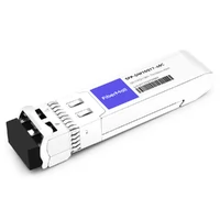
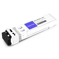
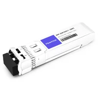
Pluggable DWDM transceivers integrate wavelength-specific or wavelength-tunable optical transmitters into compact modules that can be installed in compatible networking equipment.
Two common categories are fixed-wavelength and tunable DWDM transceivers.
A fixed-wavelength DWDM module operates at a designated optical channel. In a network using 40 different wavelengths, an operator may need multiple wavelength-specific module variants to support the complete channel plan.
This approach can be cost-effective for stable networks with relatively few assigned wavelengths, but it increases spare-part inventory requirements.
A tunable DWDM transceiver can be configured to operate at different wavelengths within its supported tuning range.
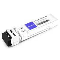
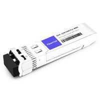
For example, some tunable 10G SFP+ DWDM modules support approximately 48 channels on a 100 GHz grid, while other implementations support different tuning ranges, channel counts, and grid spacings.
Power consumption and reach also vary by module design. Certain tunable 10G SFP+ modules consume approximately 2.0–2.5 W, but these values should be checked against the specific product datasheet.
The main advantage is inventory flexibility. Instead of stocking numerous fixed-wavelength module variants, operators can use a smaller number of tunable module types to cover multiple channel assignments.
DWDM transceivers are available in several form factors, including SFP+, XFP, QSFP-DD, and OSFP.
However, physical form-factor compatibility does not guarantee operational compatibility. The module must also match the host port’s electrical interface, supported data rate, power budget, management interface, and firmware requirements.
Coherent DWDM modules may require additional host support for DSP management, thermal control, and module configuration.
For a broader introduction to optical module operation, see FiberMall’s guide to understanding optical transceivers.
Coherent DWDM and High-Speed Transport (400G/800G)
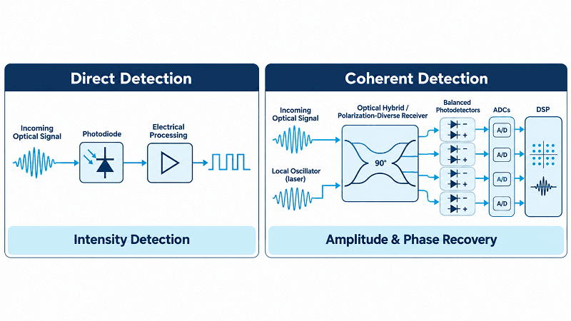
Direct-detect DWDM channels top out around 25G each over meaningful distances. To push past that, modern DWDM uses coherent detection.
Coherent vs Direct-Detect
A coherent receiver recovers four dimensions of the signal: in-phase and quadrature on each of two polarizations. With that much information, the module can use high-order modulation such as DP-16QAM and reach 400G or 800G per wavelength. Sophisticated DSP handles chromatic dispersion, polarization mode dispersion, and forward error correction in real time.
The payoff is reach. A direct-detect 400G module like FR4 covers about 2 km. A coherent module covers 120 km or more on the same fiber. That gap is why coherent optics own every 400G and 800G link that has to leave the building.
400ZR, OpenZR+, and 800ZR
Three specifications matter at 400G and 800G.
- 400ZR (OIF, 2020) defines a pluggable 400G coherent interface using DP-16QAM at roughly 60 Gbaud. It reaches 120 km amplified or 40 km unamplified and targets multi-vendor DCI.
- OpenZR+ is an MSA, not a formal standard. It adds software-selectable rates from 100G to 400G and reach beyond 300 km, which suits metro and regional meshes.
- 800ZR (OIF, October 2024) defines single-wavelength 800G for amplified point-to-point links of 80 to 120 km, drawing roughly 26 to 32 watts per module.
Pick by distance and by whether the line system is simple or ROADM-heavy. Each ROADM hop adds a filtering penalty, so a 400G channel that reaches 600 km on a point-to-point link may fall short of that across a long metro mesh.
IPoDWDM and DCI
Marco’s team ran a 90 km link between two data centers the old way. Grey optics fed a transponder shelf, which re-emitted colored light onto the line. The shelf took a rack unit, burned around 300 watts, and gave them one more box to fail. Swapping to 400ZR pluggables let the routers talk straight over the DWDM line. The shelf came out of the rack entirely.
That is IPoDWDM in one paragraph. When the router sources a colored, DWDM-ready wavelength, the photonic layer becomes pure glass and amplifiers. Fewer boxes, less power, less floor space, and one layer to operate. At 800G, the same approach drives multi-building AI clusters where coherent DSP latency stays under a microsecond. Pluggable coherent optics for these links use QSFP-DD and OSFP cages; the 1.6T OSFP platform shows where that roadmap lands next.
DWDM Network Design and Link Budget
Good DWDM design starts with the topology and ends with a power budget that closes with margin to spare.
Topologies
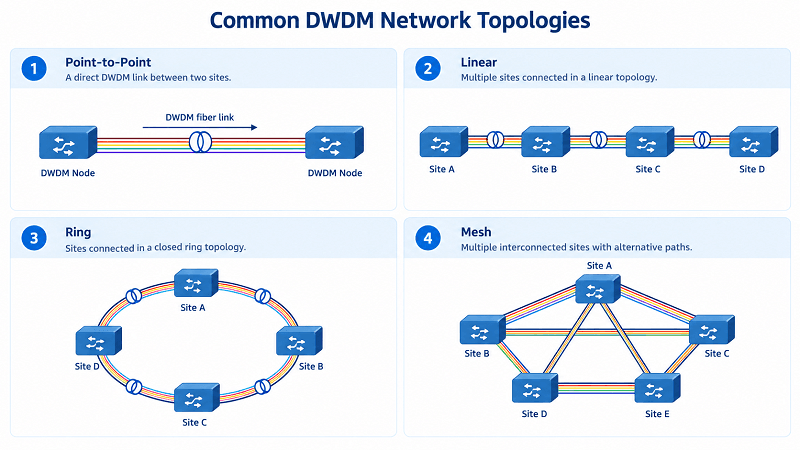
- Point-to-point links two sites directly. It’s the simplest DWDM build and the backbone of DCI, where it pairs primary and disaster-recovery data centers.
- Bus or linear links several sites in a line, with dedicated wavelengths between a central site and each remote. Protection is limited.
- Ring topologies dominate metro. A hubbed ring puts terminal mux/demux at the hub and OADMs at the spokes. A meshed ring gives every node a path to every other node through wavelength reuse.
- Mesh builds on ROADMs and WSS, allowing any-to-any paths at the optical layer.
One rule haunts every ring design: the wavelength continuity constraint. An optical circuit must use the same wavelength on every segment unless the node has a wavelength converter. Break that rule by accident and the circuit simply will not light.
Power Budget and OSNR
Take one sensible link and do the arithmetic. Two sites sit 120 km apart on standard single-mode fiber. At 1550 nm the fiber attenuates about 0.22 dB per kilometer, so the span loses roughly 26 dB. Connectors and splices add maybe 2 dB. A mux and demux at each end cost about 3 dB apiece. The budget is now near 34 dB.
One EDFA supplies about 20 dB of gain, so you place a single amplifier at the midpoint and split the span into two 60 km sections. Each section drops about 13 dB, well inside the amplifier’s comfortable range. Received power lands above receiver sensitivity with a few dB of margin for aging and repairs.
Dispersion, PMD, and Nonlinear Effects
Optical power is not free. Push too much into a fiber and nonlinear effects appear. Four-wave mixing smears channels into each other. Stimulated Brillouin and Raman scattering steal power or shift it across the spectrum. The fix is usually simple: keep channel power below the nonlinear threshold and space channels so mixing products land outside active bands.
Dispersion is the other limit. Chromatic dispersion spreads pulses as they travel, and polarization mode dispersion splits them further. Coherent DSP corrects most of it in the electrical domain, but accumulated dispersion still has to fall inside the module’s compensation range. On older 10G direct-detect links, dispersion compensation modules (DCM) handle the job in the optical domain.
The fiber type matters here too. Standard G.652 fiber works for most spans. Dispersion-shifted G.653 fiber is a poor DWDM choice because its zero-dispersion point sits right where four-wave mixing is worst. Non-zero dispersion-shifted G.655 fiber avoids that trap and is built for DWDM. Cisco’s DWDM planning guide covers the fiber and node details in depth if you want the vendor view.
The Channel Plan Saves the Day
During a ring upgrade, one team planned to reuse channel 21 at two nodes. The channel plan said it was free. It was not. An earlier add had already taken it, and the records had not caught up. Rechecking the grid before cutover surfaced the collision. They moved one link to channel 34 and cut over with no disruption. Small bookkeeping beat a two-hour outage.
DWDM vs OTN and IPoDWDM Architectures
DWDM and OTN are not competitors so much as layers. DWDM is the physical medium: many wavelengths on one fiber. OTN is a digital framing layer, defined in G.709, that adds strong forward error correction, performance monitoring, and standardized multiplexing of lower-rate services into higher-rate containers.
Traditional DWDM networks put an OTN or transponder layer between the client and the line. That layer costs money, power, and latency, but it gives operators per-service monitoring and clean handoffs. IPoDWDM collapses the layering: routers plug colored optics straight into the line, and the router handles the framing. IPoDWDM wins on cost, power, and latency. For latency-sensitive financial or AI traffic, that difference decides the design.
DWDM Applications and Use Cases
DWDM shows up anywhere fiber is scarce and demand is high.
In telecom backbones, it moves interoffice, long-haul, and extended long-haul traffic. The classic distance tiers are 0 to 300 km for interoffice, 300 to 600 km for long-haul, and 600 to 2,000 km for extended long-haul, with amplification bridging each span.
In metro rings, OADMs and ROADMs let carriers add capacity node by node without new fiber. This is where the technology pays for itself fastest, because metro ducts are the most expensive to expand.
In data center interconnect, 400ZR and 800ZR pluggables link campuses and availability zones at the lowest cost per bit for the reach.
In submarine cables, DWDM has been the standard for two decades, packing hundreds of wavelengths onto long unrepeatered and repeated spans.
And in AI and HPC clusters, multi-building deployments now lean on coherent DWDM to move training traffic between halls without a network bottleneck.
Advantages and Limitations
The advantages are clear: capacity multiplication, protocol transparency, long reach, and step-by-step scalability. The limitations are just as real. DWDM demands precise, temperature-stabilized lasers, careful temperature compensation in filters, and staff who understand optical budgets. It also has an economic floor. Moving below about 8 to 10 Gb/s per wavelength rarely pays once you count the cost of the transponders and amplifiers.
Choosing DWDM Hardware
The component list for a DWDM build is short, but each item deserves attention.
- Mux/demux: match the channel count and band to your plan. Choose TFF for small counts and AWG for 40 channels and up.
- OADM or ROADM: fixed OADMs for predictable metro rings, ROADMs when you need reconfiguration and mesh restoration.
- Amplifiers: size booster, line, and pre-amps to the span loss, and watch the noise figure.
- Transceivers: fixed for a few stable channels, tunable when spares and flexibility matter.
- Coherent optics: 400ZR or OpenZR+ for DCI, 800ZR when a single 800G wavelength fits the plan.
FiberMall builds all of these, from AAWG mux/demux units and passive OADMs to DWDM and tunable transceivers and coherent pluggables. Sourcing the full chain from one supplier keeps power budgets, connector types, and channel plans consistent across a project.
Testing, Deployment, and Troubleshooting
Commissioning a DWDM link is a sequence of measured steps. Start with a per-wavelength power check at the mux and demux to confirm launch power and received power fall in range. Next, verify OSNR on the noisiest channel, because the weakest channel usually fails first. Then run a bit error rate test or check the module’s pre-FEC and post-FEC counters.
Most field faults trace back to a short list. Low OSNR points to an amplifier problem or too many spans. Loss of signal on a single channel usually means a bad laser or a mis-patched port. A power mismatch between channels often comes down to a dirty connector or a missing attenuator. Cleaning every connector before patching prevents more outages than any other habit.
FAQ
What is DWDM and how does it work?
DWDM is dense wavelength division multiplexing. It carries many data streams on one fiber by giving each stream a distinct wavelength. A multiplexer combines the wavelengths at one end, a demultiplexer separates them at the other, and optical amplifiers boost all channels together.
How many channels does DWDM support?
The count depends on channel spacing and band. A 100 GHz C-band plan fits about 40 channels. A 50 GHz plan fits about 80. Adding the L-band roughly doubles the total, and finer flex-grid spacing pushes counts toward 160 or more.
DWDM vs CWDM: which should I use?
Choose CWDM for short metro and access links with a handful of channels, since its uncooled lasers keep costs low. Choose DWDM for long-haul, high-capacity, or amplified links, where tight spacing and EDFA support are essential.
What is the maximum DWDM distance?
Unamplified links reach about 80 to 100 km. With EDFAs, a point-to-point span can reach roughly 200 km before regeneration. With regeneration and coherent optics, DWDM spans hundreds to thousands of kilometers, limited more by OSNR and cost than by physics.
Is DWDM better than OTN?
They solve different problems. DWDM is the optical medium that carries wavelengths. OTN is a framing layer on top that adds monitoring and error correction. Many modern networks use both, and IPoDWDM drops the OTN layer entirely where cost and latency matter most.
Conclusion
DWDM is the highest-capacity technique in fiber optic networking, and it turns a fixed fiber plant into a scalable asset. Five points capture the essentials:
- It packs 40 to 160+ independent channels onto a single fiber pair.
- Channel spacing defines capacity, from 100 GHz for simplicity to 50 GHz and finer for density.
- The ITU-T G.694.1 grid keeps every laser on the same wavelength plan.
- Mux/demux, OADMs, ROADMs, and EDFAs form the physical chain that makes a link work.
- Coherent optics and IPoDWDM now push DWDM into the data center itself at 400G and 800G.
If you are planning a DWDM build, the design decisions come before the shopping list. Share your topology, distances, and channel count with FiberMall, and our engineers will map the components and optics that fit. Request a DWDM design consultation and get a channel plan built for your link.
Related Products:
-
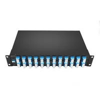
 DWDM MUX DEMUX 50GHZ 96CH (C15-C62) LC/UPC Dual Fiber 2U Rack
$6000.00
DWDM MUX DEMUX 50GHZ 96CH (C15-C62) LC/UPC Dual Fiber 2U Rack
$6000.00
-
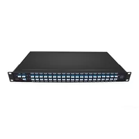
DWDM MUX DEMUX 40CH (C21-C60) LC/UPC Dual Fiber 1U Rack
$1100.00
-
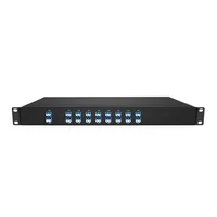
DWDM MUX DEMUX 16CH (C21-C36) with Monitor Port LC/UPC Dual Fiber 1U Rack
$800.00
-
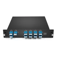
DWDM MUX DEMUX 8CH (C21-C28) with Express Port LC/UPC Dual Fiber LGX BOX
$500.00
-
DWDM MUX 8CH 16 Wavlengths (TX: C43/C45/C47/C49/C51/C53/C55/C57 RX: C44/C46/C48/C50/C52/C54/C56/C58) with MON Port LC/UPC Single Fiber LGX BOX
$450.00
-
SFP-DW10G17-40C 10G DWDM SFP+ C17 100GHz 1563.86nm 40km LC SMF DDM Transceiver Module
$155.00
-
SFP-DW10G17-80C 10G DWDM SFP+ C17 100GHz 1563.86nm 80km LC SMF DDM Transceiver Module
$175.00
-
SFP-DW10G17-100C 10G DWDM SFP+ C17 100GHz 1563.86nm 100km LC SMF DDM Transceiver Module
$235.00
-
SFP-DW10GTU-40C 10G DWDM Tunable SFP+ 50GHz 1529.55nm~1561.83nm 40km LC SMF DDM Transceiver Module
$550.00
-
SFP-DW10GTU-80C 10G DWDM Tunable SFP+ 50GHz 1529.55nm~1561.83nm 80km LC SMF DDM Transceiver Module
$750.00