An Ethernet switch is a network device used to connect multiple computers and other network devices in local area network (LAN). It acts like a transportation hub, transporting data packets from one device to another.
Ethernet switches connect computers, servers, printers and other devices through physical ports, and forward data packets from the source device to the target device based on the destination MAC address (Media Access Control) of the data packet. This forwarding process is based on the forwarding table inside the switch.
When a packet arrives at the switch, the switch checks the destination MAC address in the packet and matches that address to its internal forwarding table. If the target MAC address exists in the forwarding table, the switch will forward the data packet directly to the port connected to the target device; If the destination MAC address is not in the forwarding table, the switch broadcasts the packet to all other ports in order to find the destination device.
In short, an Ethernet switch is an important network device, used to achieve high-speed and reliable data transmission in LAN, and to provide flexible network management and security functions. It is one of the indispensable infrastructures in modern networks.
Definition and Classification of Switch
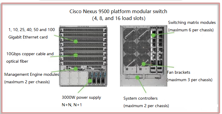
In terms of hardware structure, the switch consists of a chassis, power supply, fan, backplane, management engine, system controller, switching module, and line card. The chassis is the shell of the switch, used to protect the internal electronic components. Some switches use a metal casing to prevent magnetic fields from interfering with the switch. The fan is used to dissipate heat from the switch to ensure that the internal temperature of the switch is within a normal range and ensure long-term stable operation of the switch. The power supply includes an external power supply and a built-in power supply. The external power supply can provide flexible power configuration. Backplane in a chassis switch is a PCB board used to connect the management engine, switching modules, line cards and other parts.
- Management engine: There is a configuration port on the management engine, which is a serial interface and can be connected to a computer through a serial cable for management and configuration of the switch.
- System controller: Responsible for controlling the power supply and fans.
- Line card: It can be used to configure the Ethernet interface and connect to the computer or other hardware devices through the Ethernet interface for data transmission.
- Switching module: Responsible for data forwarding and switching between different interfaces. The switching unit uses high-performance ASIC chips.
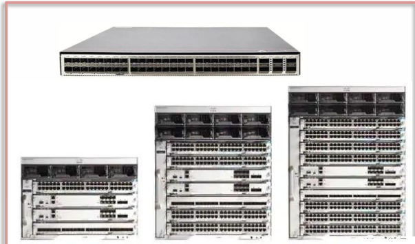
Appearance of box-type and chassis switches
Switch architecture
Three mainstream architectures in the industry: Full-MESH architecture; CROSSBAR architecture; CLOS architecture. Most of the current mainstream high-end core switches adopt CLOS architecture.
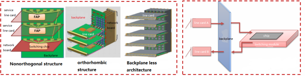
Switching network board design based on CLOS architecture:
- Non-orthogonal structure/parallel structure: The line card and the switching module are parallel, and the two are connected through wiring on backplane. Huawei’s switches use a non-orthogonal design. Disadvantages: PCB backplane writing brings signal interference, and backplane design limits broadband upgrades and heat dissipation.
- Orthogonal structure: The line card and the switching module are vertical and directly connected through backplane. This design reduces the signal attenuation caused by backplane wiring but limits the bandwidth upgrade. Cisco uses the orthogonal structure.
- Backplane-less architecture: The line cards and switching modules are vertically connected, which relieves backplane restrictions on broadband upgrades and facilitates heat dissipation.
The working mechanism of the switching module: The data transmission path from line card A to line card B is line card A →backplane → switching module →switching chip.
Design of switching module architecture
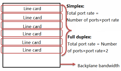
Switch performance metric:
Assumption: number of ports =number of lanes; backplane bandwidth =the number of cars passing on the road per unit time; Exchange capacity =the number of vehicles the intersection commander can direct to pass through the intersection safely without obstruction in a unit time.
If a maximum of 1,000 cars can run on the road per unit time, and the intersection commander’s command ability is strong enough, then a maximum of 1,000 cars can run on the road with an intersection, which is equivalent to the switch reaching the line speed indicator.
However, if the intersection commander’s command ability is insufficient and he can only direct 500 vehicles to pass smoothly per unit time, then at most 500 vehicles can run smoothly on the road with the intersection, which means the line speed indicator is not reached. That is, to achieve non-blocking data exchange, the data transmission speed must meet the requirements of full-duplex port: backplane bandwidth ≥number of ports ×port speed ×2; and at the same time, switching capacity ≥port number X port speed.
Currently, switches that use switching matrices can generally achieve line speed indicators. For example, Cisco uses switching matrix modules. Generally speaking, backplane bandwidth is of little significance, while switching capacity and packet forwarding rate are key indicators that reflect switch performance.
port rate
Switch application scenarios:
Classified according to the application scenarios of switches: commercial switches and industrial switches. Commercial switches are classified according to application scenarios: enterprise network switches (SMB switches), campus switches, and data center switches.
The network layer of the campus network adopts the industry’s mature three-layer architecture:
Access switch: Access layer switches are generally deployed in network cabinets in corridors to access campus network users (PCs or servers).They provide layer 2 switch functions and also support layer 3 access functions(access switches are Layer 3 Switch). Since access layer switches are directly connected to campus network users, there are higher requirements for the density of GE/FE interfaces on access switches based on the number and type (GE/FE) of user access information points. In addition, access switches are deployed in corridor network cabinets, which are large in number and have high requirements for cost, power consumption, and management and maintenance.
Aggregation switch: Campus aggregation layer switches are generally deployed in independent network aggregation cabinets in buildings to aggregate traffic from campus access switches. They generally provide layer 3 switch functions. Aggregation layer switches, as the gateway of the campus network, terminate the layer 2 traffic of campus network users and perform Layer 3 forwarding. As needed, value-added service boards (such as firewalls, load balancers, and WLAN AC controllers) can be integrated on the aggregation switches or independent value-added service devices can be attached to provide value-added services to campus network users.
Core switch: The core layer switch of the campus is deployed in the core computer room of the campus. It aggregates user traffic between buildings and areas, provides layer 3 switch functions. “Vertical traffic” connecting the external network of the campus to internal users and “Horizontal traffic” between users in different aggregation areas require high-density 10GE and high forwarding performance.
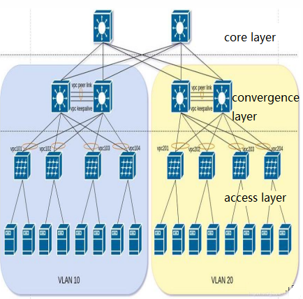
Network topology in data center switch:
Traditional three-layer network architecture: including the core switching layer that interconnects the data center and external operators, the access layer, and the aggregation layer that connects the two to achieve data aggregation. Today’s data center network is mainly divided into three-layer topology.
- The access switch physically connects to the server.
- The aggregation switch connects the access switches under the same Layer 2 network (VLAN)and provides other services, such as firewall, SSL offload, intrusion detection, network analysis, etc. It can be a Layer 2 switch or a Layer 3 switch.
- Core switches provide high-speed forwarding of packets in and out of the data center, providing connectivity to multiple Layer 2 LANs (VLANs). They typically provide a resilient Layer 3 network for the entire network.
Traditional three-layer structure of data center
Data center switches—leaf-spine architecture
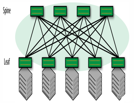
Leaf-spine architecture: also called distributed core network. Since this network architecture is derived from the Switch Fabric inside the switch, it is also called Fabric network architecture, belonging to CLOS network model. The Spine-Leaf network architecture has been proven to provide high-bandwidth, low-latency non-blocking server-to-server connections.
The data center network topology consists of two switching layers, Spine and Leaf.
The leaf layer consists of access switches that aggregate traffic from servers and connect directly to the spine or network core.
Spine switches interconnect all Leaf switches in a full mesh topology. In the figure above, green nodes represent switches and gray nodes represent servers. Among the green nodes, the top one is the Spine node, and the bottom one is the Leaf node.
Spine-Leaf architecture is suitable for the needs of modern applications
- Flat design: flat design shortens communication paths between servers, thereby reducing latency and can significantly improve application and service performance.
- Easy to expand: If the bandwidth of the Spine switch is insufficient, we only need to increase the number of Spine nodes or provide load balancing on the path; If there are insufficient access connections, just increase the number of Leaf nodes.
- Low convergence ratio: It is easy to achieve a convergence ratio of 1:X or even a non-blocking 1:1, and the link convergence ratio can also be reduced by increasing the link bandwidth between Spine and Leaf devices. Simplified management: The leaf-spine structure can use every link in the full mesh for load balancing in a loop-free environment. This equal-cost multipath design is at its best when using a centralized network management platform such as SDN.
- Edge traffic processing: With the rise of services such as the Internet of Things (loT), the pressure on the access layer has increased dramatically. There may be thousands of sensors and devices connected at the edge of the network and generating a large amount of traffic. Leaf can handle connections at the access layer, and Spine ensures non-blocking performance with very low latency between any two ports within a node, thereby enabling agile services from access to the cloud platform.
- Multi-cloud management: data centers or clouds can achieve high performance, high fault tolerance, and other advantages through the Leaf Spine architecture, and multi-cloud management strategies have gradually become a must for enterprises.
Data center leaf-spine structure
Related Products:
-
 QSFP28-100G-SR4 100G QSFP28 SR4 850nm 100m MTP/MPO MMF DDM Transceiver Module
$40.00
QSFP28-100G-SR4 100G QSFP28 SR4 850nm 100m MTP/MPO MMF DDM Transceiver Module
$40.00
-
QSFP28-100G-DR1 100G QSFP28 Single Lambda DR 1310nm 500m LC SMF with FEC DDM Optical Transceiver
$180.00
-
QSFP28-100G-LR1 100G QSFP28 Single Lambda LR 1310nm 10km LC SMF with FEC DDM Optical Transceiver
$265.00
-
QSFP28-100G-ER4L 100G QSFP28 ER4 Lite 1310nm (LAN WDM) 40km with FEC,30km without FEC LC SMF DDM Transceiver Module
$800.00
-
QSFP-DD-400G-SR8 400G QSFP-DD SR8 PAM4 850nm 100m MTP/MPO OM3 FEC Optical Transceiver Module
$149.00
-
QSFP-DD-400G-DR4 400G QSFP-DD DR4 PAM4 1310nm 500m MTP/MPO SMF FEC Optical Transceiver Module
$400.00
-
QSFP-DD-400G-FR4 400G QSFP-DD FR4 PAM4 CWDM4 2km LC SMF FEC Optical Transceiver Module
$500.00
-
QSFP-DD-400G-SR4.2 400Gb/s QSFP-DD SR4 BiDi PAM4 850nm/910nm 100m/150m OM4/OM5 MMF MPO-12 FEC Optical Transceiver Module
$900.00
-
SFP-10G31-LRI 10G SFP+ LR 1310nm 10km LC SMF DDM Industrial High Temperature Transceiver Module
$20.00
-
SFP-10G85-SRI 10G SFP+ SR 850nm 300m LC MMF DDM Industrial High Temperature Transceiver Module
$13.00
-
SFP-10G-TS80 10GBase-T Copper SFP+ to RJ45 80m Transceiver Module
$55.00
-
SFP-10G55-ZR100 10G SFP+ ZR 1550nm 100km LC SMF DDM Transceiver Module
$280.00