In the market, there are different versions of the ratio of optical transceivers to the number of GPUs, and the figures of various versions are not consistent mainly because the amount of optical modules required under different networking architectures is not the same. The actual number of optical modules used mainly depends on the following aspects.
1) NIC Models
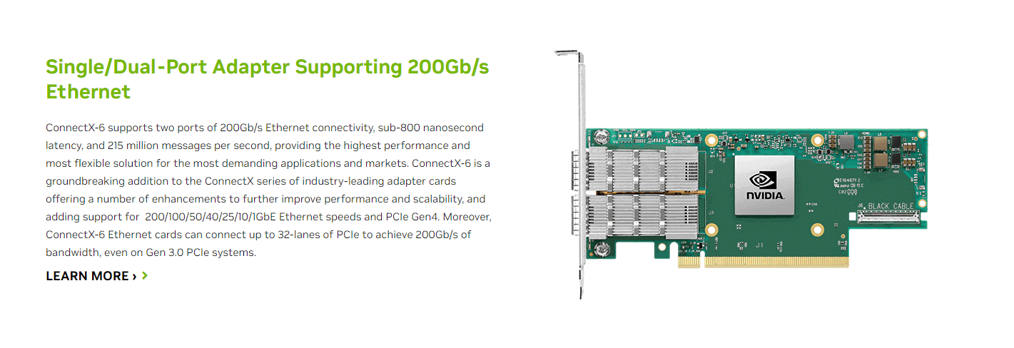
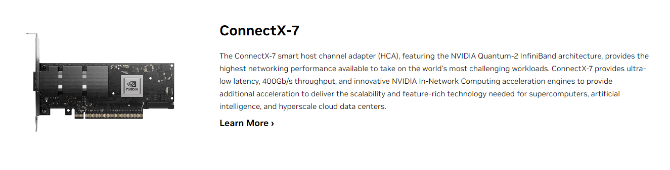
Mainly includes two types of network cards, ConnectX-6 (200Gb / s, mainly used with the A100) mainly used optical modules are MMA1T00-HS (200G Infiniband HDR QSFP56 SR4 PAM4 850nm 100m) and ConnectX-7 (400Gb/s, mainly used with H100).
2) Switch Models
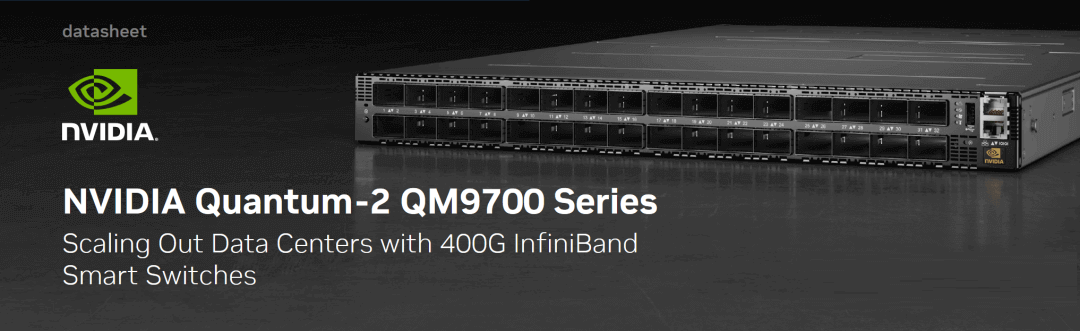
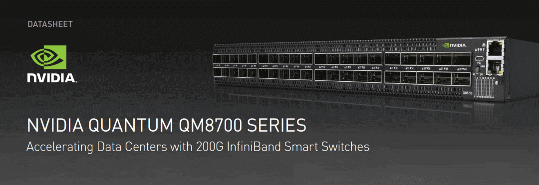
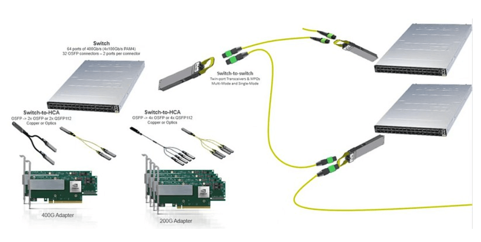
The next-generation ConnectX-8 800Gb/s switch model mainly includes two types of switches, the QM9700 series (32-port OSFP (2*400Gb/s), with a total of 64 channels at 400Gb/s transfer rate, totaling 51.2Tb/s throughput rate) and the QM8700 series (40-port QSFP56, with a total of 40 channels at 200Gb/s, totaling 16Tb/s throughput rate).
3) Number of units (Scalable unit SU)
The number of units affects the level of switching architecture, only two-layer architecture is used when the number of units is small, and three-layer architecture is used when the number of units is large.
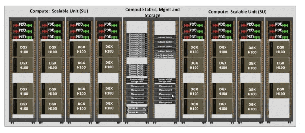
H100 SuperPOD: Each unit consists of 32 nodes (DGX H100 servers), and supports a maximum of 4 units to form a cluster with a two-layer switching architecture.
A100 SuperPOD: each unit includes 20 nodes (DGX A100 server), supports a maximum of 7 units to form a cluster, and more than 5 units require a three-tier switching architecture.
Conclusion:
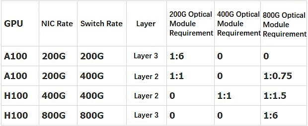
(1) A100+ConnectX6+QM8700 three-layer network: 1:6 in ratio, all with 200G QSFP56 optical modules
(2) A100+ConnectX6+QM9700 two-layer network: 1:0.75 800G OSFP transceivers + 1:1 200G QSFP56 optical modules
(3) H100+ConnectX7+QM9700 two-layer network: 1:1.5 800G OSFP optical modules + 1:1 400G OSFP optical module
(4) H100+ConnectX8 (not yet released) + QM9700 three-layer network: 1:6 ratio, all with 800G OSFP transceivers
Assuming that 300,000 H100 + 900,000 A100 are shipped in 2023, a total of 3.15 million 200G QSP56 + 300,000 400G OSFP + 787,500 800G OSFP demand will be generated, resulting in an incremental AI market space of $1.38 billion.
Assuming 1.5 million H100s + 1.5 million A100s are shipped in 2024, a total of 750,000 200G QSFP56s + 750,000 400G OSFPs + 6.75 million 800G OSFPs demand is generated, bringing in an incremental market space of $4.97 billion for AI (approximately equal to the sum of the 2021 digital pass-through optical module market size).
Below is the detailed measurement process for each of the above scenarios.
Scenario 1: A100+ConnectX6+QM8700 three-layer network.
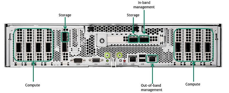
A100 has a total of eight computing interfaces, four on the left and four on the right in the figure. Currently, A100 shipments are mainly paired with ConnectX6 for external communication, with an interface rate of 200Gb/s.
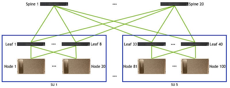
In the first layer architecture, each node (Node) has 8 interfaces (Port), each node is connected to 8 leaf switches (Leaf), and every 20 nodes form a unit (SU), so in the first layer a total of 8*SU leaf switches are needed, 8*SU*20 cables (Cable) are needed, and 2*8*SU*20 200G optical transceivers are needed.
In the Layer 2 architecture, the uplink rate is equal to the downlink rate due to the non-blocking architecture. In Layer 1, the total unidirectional transmission rate is 200G*number of cables. Since Layer 2 also adopts a single cable 200G transmission rate, the number of cables in Layer 2 should be the same as that in Layer 1, requiring 8*SU*20 cables (Cable) and 2*8*SU*20 200G transceivers. The number of ridge switches (Spine) required is the number of cables divided by the number of leaf switches, requiring (8*SU*20)/(8*SU) ridge switches. But when the number of leaf switches is not large enough, more than two connections can be made between the leaf and the ridge in order to economize on the number of ridge switches (as long as the 40-interface limit is not exceeded). Therefore, when the number of units is 1/2/4/5 respectively, the number of required ridge switches is 4/10/20/20, and the number of required optical modules is 320/640/1280/1600 respectively, the number of ridge switches will not be increased in the same proportion, but the number of transceivers will be increased in the same proportion.
When the number of units reaches 7, the third layer of the architecture is required, due to the non-blocking architecture so the number of cables required for the third layer of the architecture is the same as the number of the second layer.
NVIDIA recommended configuration SuperPOD: NVIDIA recommended 7 units for networking, need to increase the Layer 3 architecture and increase the core switch (Core), a variety of different numbers of units of each layer of the number of switches, the number of cables connected to the figure shown.
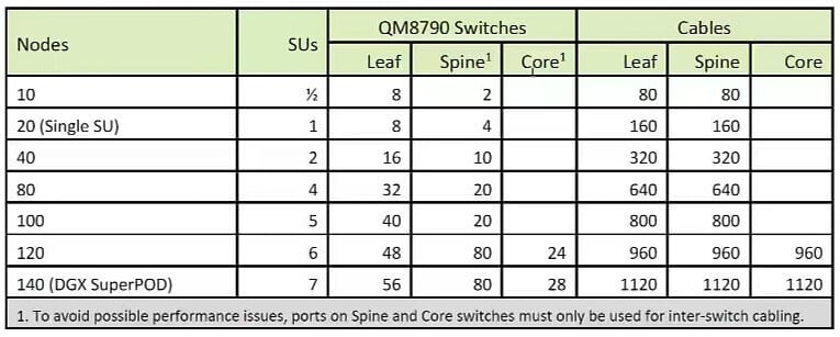
140 servers, a total of 140*8=1120 A100s, a total of 56+56+28=140 switches (QM8790), 1120+1120+1120=3360 cables, 3360*2=6720 200G QSFP56 optical modules, The mapping between the A100 and 200G QSFP56 transceivers is 1120/6720=1:6.
Scenario 2: A100+ConnectX6+QM9700 Layer 2 network
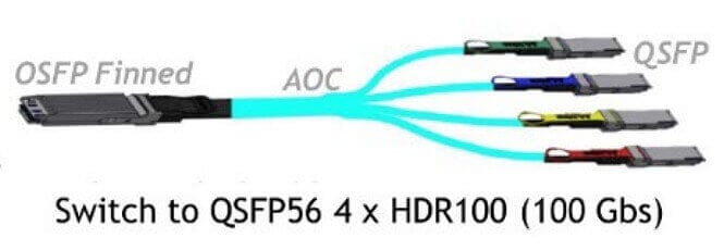
At present, this solution is not available in the recommended configuration, but in the future, more and more A100s may choose QM9700 networking, which will reduce the number of optical transceivers used, but bring 800G OSFP optical module requirements. The biggest difference is that the first layer connection is converted from 8 external 200G cables to a QSFP to OSFP interface with 2 and 1 to 4.
In the first layer: for a 7-unit cluster, 140 servers have 140 * 8 = 1120 interfaces, with a total of 1120/4 = 280 1-tow-4 cables connected externally, resulting in 280 800G OSFP and 1120 200G OSFP56 optical module requirements. A total of 12 QM9700 switches are required.
At Layer 2: with only 800G connections, 280*2=560 800G OSFP transceivers are needed, requiring 9 QM9700 switches.
Therefore, 140 servers and 1120 A100s require 12+9=21 switches, 560+280=840 800G OSFP optical modules, and 1120 200G QSFP56 optical transceivers.
The mapping between A100 and 800G OSFP optical module is 1120:840 =1:0.75, and the mapping between A100 and 200G QSFP56 optical module is 1:1
Scenario 3: H100+ConnectX7+QM9700 Layer 2 network
The special point of the H100 design is that although the network card is eight Gpus with eight 400G network cards, the interface is merged into four 800G interfaces, which will bring a large number of 800G OSFP optical module requirements.
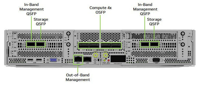
At Layer 1, according to NVIDIA’s recommended configuration, it is recommended to connect one [2*400G] 800G OSFP optical module to the server interface: MMA4Z00-NS (800Gb/s Twin-port OSFP 2x400G SR8 PAM4 850nm 100m DOM Dual MPO-12 MMF) or MMS4X00-NM ( 800Gb/s Twin-port OSFP 2x400G PAM4 1310nm 500m DOM Dual MTP/MPO-12 MMF), via twin-port. ), two fiber optic cables (MPOs) are connected via twin-port and plugged into each of the two switches.
So for the first layer, one unit contains 32 servers, one server is connected to 2*4=8 switches, and SuperPOD includes 4 units, which requires a total of 4*8=32 leaf switches to be connected at the first layer.
NVIDIA suggests that you need to set aside a node for management purposes (UFM), due to the limited impact on the use of optical transceivers we just follow the 4 units of 128 servers in accordance with the abbreviated calculation.
In the first layer, a total of 4*128 = 512 800G OSFP optical modules, and 2*4*128 = 1024 400G OSFP optical modules: MMA4Z00-NS400 (400G OSFP SR4 PAM4 850nm 30m on OM3/50m on OM4 MTP/MPO-12) or NVIDIA MMS4X00-NS400 (400G OSFP DR4 PAM4 1310nm MTP/MPO-12 500m).
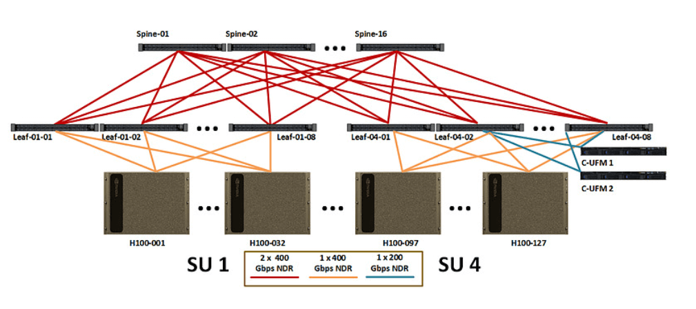
At Layer 2, the switches are directly connected to each other with 800G optical modules, and one leaf switch is connected downward at a unidirectional rate of 32*400G. In order to ensure that the upstream and downstream rates are the same, so the upward connection requires 16*800G unidirectional rate, requiring 16 ridge switches, a total of 4*8*16*2=1024 800G optical transceivers.
Therefore, under this architecture, the two layers need a total of 512+1024=1536 800G OSFP optical modules and 1024x400G OSFP optical transceivers, a total of 4*32*8=1024 H100. Therefore, the mapping between the GPU and the 800G OSFP optical module is 1024/1536→ 1:1.5, and the mapping between the GPU and the 400G OSFP optical module is 1024/1024 → 1:1.
Scenario 4: H100+ConnectX8 (not yet released) + QM9700 Layer 3 network
This scenario has not been released yet, but let’s assume that after the H100 is also upgraded to an 800G NIC, the external interfaces should be upgraded from 4 OSFP interfaces to 8 OSFP interfaces. The connection between each layer is connected with 800G, and the whole network architecture is similar to the first scenario, only the 200G optical module is replaced with 800G optical module. Therefore, the ratio of GPUs to optical modules in this architecture is also 1:6.
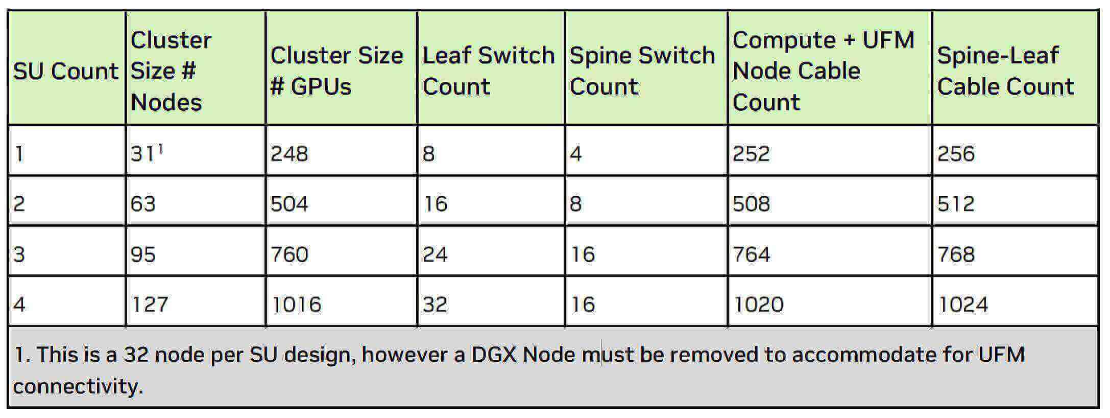
We organize the above four scenarios into the following table.
Assume that 300,000 H100+ 900,000 A100 will be shipped in 2023, bringing a total of 3.15 million 200G+ 300,000 400G+ 787,500 800G OSFP demand.
Assume that 1.5 million H100+ 1.5 million A100 will be shipped in 2024, bringing a total of 750,000 200G+ 750,000 400G+ 6.75 million 800G OSFP demand.
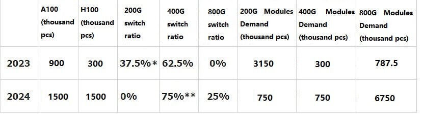
* Half of the A100 uses 200G switches and half uses 400G switches.
** Half of the H100 uses 400G switches and half uses 800G switches.
The above estimates of A100 H100 quantities are assumptions only and do not represent future expectations.
According to the simple calculation of the average price of $1 /GB in 2023 and $0.85 /GB in 2024, AI is expected to bring 13.8/ 4.97 billion US dollars of AI incremental market space for optical transceivers.
Related Products:
-
 NVIDIA(Mellanox) MMA1T00-HS Compatible 200G Infiniband HDR QSFP56 SR4 850nm 100m MPO-12 APC OM3/OM4 FEC PAM4 Optical Transceiver Module
$139.00
NVIDIA(Mellanox) MMA1T00-HS Compatible 200G Infiniband HDR QSFP56 SR4 850nm 100m MPO-12 APC OM3/OM4 FEC PAM4 Optical Transceiver Module
$139.00
-
NVIDIA MMA4Z00-NS Compatible 800Gb/s Twin-port OSFP 2x400G SR8 PAM4 850nm 100m DOM Dual MPO-12 MMF Optical Transceiver Module
$650.00
-
NVIDIA MMS4X00-NM Compatible 800Gb/s Twin-port OSFP 2x400G PAM4 1310nm 500m DOM Dual MTP/MPO-12 SMF Optical Transceiver Module
$900.00
-
NVIDIA MMA4Z00-NS400 Compatible 400G OSFP SR4 Flat Top PAM4 850nm 30m on OM3/50m on OM4 MTP/MPO-12 Multimode FEC Optical Transceiver Module
$550.00
-
NVIDIA MMS4X00-NS400 Compatible 400G OSFP DR4 Flat Top PAM4 1310nm MTP/MPO-12 500m SMF FEC Optical Transceiver Module
$700.00
-
QSFP56-200G-SR4M 200G QSFP56 SR4 PAM4 850nm 100m MTP/MPO APC OM3 FEC Optical Transceiver Module
$139.00
-
QSFP56-200G-FR4S 200G QSFP56 FR4 PAM4 CWDM4 2km LC SMF FEC Optical Transceiver Module
$650.00
-
OSFP-400G-SR4-FLT 400G OSFP SR4 Flat Top PAM4 850nm 30m on OM3/50m on OM4 MTP/MPO-12 Multimode FEC Optical Transceiver Module
$550.00
-
OSFP-400G-LR4 400G LR4 OSFP PAM4 CWDM4 LC 10km SMF Optical Transceiver Module
$1199.00
-
OSFP-400G-DR4+ 400G OSFP DR4+ 1310nm MPO-12 2km SMF Optical Transceiver Module
$850.00
-
OSFP-2x200G-FR4 2x 200G OSFP FR4 PAM4 2x CWDM4 CS 2km SMF FEC Optical Transceiver Module
$1500.00
-
OSFP-400G-DR4 400G OSFP DR4 PAM4 1310nm MTP/MPO-12 500m SMF FEC Optical Transceiver Module
$800.00
-
OSFP-400G-SR8 400G SR8 OSFP PAM4 850nm MTP/MPO-16 100m OM3 MMF FEC Optical Transceiver Module
$400.00
-
OSFP-800G-FR8L OSFP 800G FR8 PAM4 CWDM8 Duplex LC 2km SMF Optical Transceiver Module
$3000.00
-
OSFP-800G-FR8 OSFP 8x100G FR PAM4 1310nm MPO-16 2km SMF Optical Transceiver Module
$1200.00
-
OSFP-800G-LR8 OSFP 8x100G LR PAM4 1310nm MPO-16 10km SMF Optical Transceiver Module
$1800.00
-
OSFP-800G-DR8 OSFP 8x100G DR PAM4 1310nm MPO-16 500m SMF DDM Optical Transceiver Module
$900.00
-
QSFP-DD-800G-FR8L QSFP-DD 800G FR8 PAM4 CWDM8 2km DOM Duplex LC SMF Optical Transceiver Module
$3000.00