
Two DWDM transceivers can both be labeled “channel 29” and still fail to establish a link. The channel label does not uniquely identify the optical frequency. Different vendors may use different numbering conventions, while the transceivers and filters must operate at compatible frequencies for the link to work.
If you’ve ever troubleshot an optical link that should have worked, you know how much time a frequency mismatch can waste. During a network cutover, a seemingly minor channel-label discrepancy can turn into a lengthy troubleshooting session.
This guide explains what a DWDM channel really is, how the ITU-T G.694.1 grid defines it, how many channels can fit in the C-band and L-band, how 50 GHz and 100 GHz spacing compare in practice, and how to build a channel plan that supports future upgrades. We’ll also walk through a 40-channel plan and show how accurate channel assignments help prevent conflicts.
New to dense wavelength division multiplexing? Start with our DWDM complete guide, then return here for a channel-level reference.
What Is a DWDM Channel?
A DWDM channel is an optical signal centered at a nominal frequency defined by the ITU-T G.694.1 frequency grid. Each channel uses a designated portion of the optical spectrum, allowing multiple independent optical signals to share the same fiber without interfering when the system is properly designed.
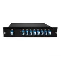
A channel is not tied to a particular network protocol. Depending on the transceiver and system design, it can carry 10G Ethernet, 100G coherent traffic, or other supported services. A multiplexer (MUX) combines multiple optical channels onto a fiber, while a demultiplexer (DEMUX) separates them at the receiving end. The fundamentals are covered in our guide to how MUX and DEMUX work.
Channel vs. Wavelength vs. Frequency
The three terms describe the same slot from different angles. A DWDM wavelength is the slot measured in nanometers; frequency is measured in terahertz. The two are related by λ = c / f.
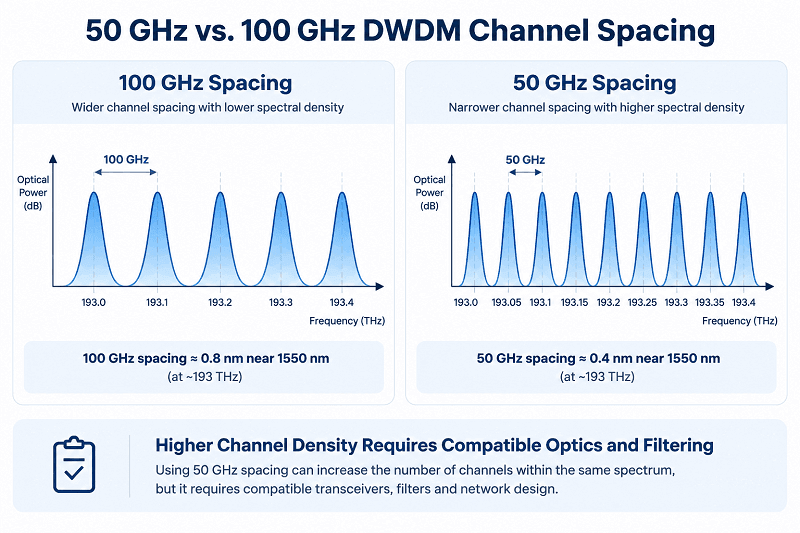
Near 1550 nm, a frequency difference of 100 GHz corresponds to approximately 0.8 nm in wavelength, while 50 GHz corresponds to approximately 0.4 nm. The conversion is not constant across the spectrum, which is one reason frequency is preferred when defining DWDM channel assignments.
In everyday conversation, engineers often use “wavelength” to mean a DWDM channel. In a channel plan, however, the nominal center frequency should be the primary identifier, with wavelength serving as a convenient reference.
Why Two “Channel 29” Ports Can Still Fail
Consider an illustrative troubleshooting scenario at a regional colocation provider. Two 10G DWDM SFP+ modules are both labeled channel 29, but the optical link remains down after installation.
The datasheets reveal the problem. One vendor assigns channel 29 to 192.9 THz, while the other vendor’s numbering scheme assigns its channel 29 to 193.1 THz. The two frequencies differ by 200 GHz, equivalent to approximately 1.6 nm near the C-band.
The transceivers are operating at different frequencies, despite carrying the same channel label.
The solution is to align the optical frequencies. If the transceivers are tunable, both can be configured to a common supported frequency. If they are fixed-wavelength modules, the mismatched module must be replaced with one operating at the required frequency.
In this illustrative case, the link comes up after the frequency mismatch is corrected. The lesson is straightforward: always verify the actual optical frequency rather than relying on a channel label alone.
The ITU-T G.694.1 Grid Behind Every DWDM Channel
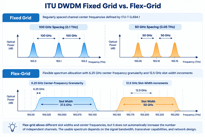
Every fixed DWDM grid is anchored at 193.1 THz, which is 1552.52 nm. The ITU-T G.694.1 recommendation defines the allowed spacings: 12.5, 25, 50, and 100 GHz, plus wider options.
The math’s simple. Any fixed-grid frequency follows f = 193.1 THz + n × spacing, where n is an integer. A 100 GHz plan steps in 0.1 THz increments. A 50 GHz plan steps in 0.05 THz.
The flex grid works differently. Center frequencies can move in 6.25 GHz steps, and the minimum slot width is 12.5 GHz. Coherent systems use it to pack spectrum more tightly than a fixed grid allows.
How C-Band Channel Numbers Map to Frequencies
On the common 100 GHz C-band plan, the labels follow a predictable pattern:
- C21 = 192.1 THz = 1560.61 nm
- C31 = 193.1 THz = 1552.52 nm
- C60 = 196.0 THz = 1529.55 nm
For channels in this range, f = 193.1 + (N − 31) × 0.1 THz. The “C” prefix means C-band. The number rises as frequency rises and wavelength falls.
Fifty-gigahertz plans use the same letter but a different numbering scheme. A 96-channel unit is often labeled C15 to C62: that label range spans 48 100 GHz intervals, and the unit carries two 50 GHz channels inside each interval. The grid covers roughly 191.5 to 196.2 THz, or about 1528.0 to 1565.5 nm. Check the datasheet for the exact sub-slot endpoints, because vendors differ at the edges.
Why Vendor Channel Tables Disagree
Channel numbers are local conventions, not physics. Some tables start “channel 1” at the low-frequency end. Others count down from the high end. Some skip band-edge channels; others include them.
The IEEE 802.3ct work on 100 Gb/s DWDM links gives a useful example: 48 channels at 100 GHz spacing, spanning 191.4 to 196.1 THz. That range doesn’t line up neatly with a C21 to C60 plan, and it isn’t supposed to. It’s a defined subset for a specific application.
Cisco’s ONS 15454 planning guides make the same point from the equipment side. The vendor channel plans depend on the platform, the card, and the band in use.
The rule that saves time: frequency is authoritative. A channel label is a convenience that only means something inside one vendor’s table.
100 GHz C-Band Channel Reference (C21–C60)
| Channel | Frequency (THz) | Wavelength (nm) |
| C21 | 192.1 | 1560.61 |
| C22 | 192.2 | 1559.79 |
| C23 | 192.3 | 1558.98 |
| C24 | 192.4 | 1558.17 |
| C25 | 192.5 | 1557.36 |
| C26 | 192.6 | 1556.55 |
| C27 | 192.7 | 1555.75 |
| C28 | 192.8 | 1554.94 |
| C29 | 192.9 | 1554.13 |
| C30 | 193.0 | 1553.33 |
| C31 | 193.1 | 1552.52 |
| C32 | 193.2 | 1551.72 |
| C33 | 193.3 | 1550.92 |
| C34 | 193.4 | 1550.12 |
| C35 | 193.5 | 1549.32 |
| C36 | 193.6 | 1548.51 |
| C37 | 193.7 | 1547.72 |
| C38 | 193.8 | 1546.92 |
| C39 | 193.9 | 1546.12 |
| C40 | 194.0 | 1545.32 |
| C41 | 194.1 | 1544.53 |
| C42 | 194.2 | 1543.73 |
| C43 | 194.3 | 1542.94 |
| C44 | 194.4 | 1542.14 |
| C45 | 194.5 | 1541.35 |
| C46 | 194.6 | 1540.56 |
| C47 | 194.7 | 1539.77 |
| C48 | 194.8 | 1538.98 |
| C49 | 194.9 | 1538.19 |
| C50 | 195.0 | 1537.40 |
| C51 | 195.1 | 1536.61 |
| C52 | 195.2 | 1535.82 |
| C53 | 195.3 | 1535.04 |
| C54 | 195.4 | 1534.25 |
| C55 | 195.5 | 1533.47 |
| C56 | 195.6 | 1532.68 |
| C57 | 195.7 | 1531.90 |
| C58 | 195.8 | 1531.12 |
| C59 | 195.9 | 1530.33 |
| C60 | 196.0 | 1529.55 |
Wavelengths are rounded to two decimals. Always confirm the exact grid against the module datasheet before you program a tunable optic.
100 GHz vs. 50 GHz DWDM Channel Spacing
DWDM channel spacing is the frequency difference between adjacent nominal channel center frequencies on the grid. It affects how closely channels can be packed onto a fiber and how much spectral room is available for each optical signal.
At 100 GHz spacing, adjacent channels are approximately 0.8 nm apart near 1550 nm. A conventional C-band plan commonly accommodates around 40 channels. At 50 GHz spacing, the separation decreases to approximately 0.4 nm, allowing around 80 channels in a comparable C-band allocation. Extended C-band systems and specific equipment designs may support more.
However, doubling the nominal channel density does not automatically double the usable system capacity. The optics, filters, amplifiers, and transmission conditions must all support the selected grid.
Filter passbands are particularly important. For example, some filter specifications show a 3 dB passband of approximately 75 GHz for a 100 GHz grid and approximately 41 GHz for a 50 GHz grid. These are example values rather than universal requirements. Narrower passbands leave less room for signal bandwidth and frequency deviation.
In strongly filtered systems, particularly those with cascaded ROADMs, passband narrowing can introduce additional transmission penalties and reduce the available OSNR margin. The actual penalty depends on the filter design, modulation format, signal bandwidth, and number of filtering stages.
Compatibility matters just as much. A transceiver designed for a 50 GHz grid may work through a 100 GHz MUX port if its center frequency aligns with the port and its signal spectrum fits within the filter passband. However, a 100 GHz port cannot be assumed to pass two independent 50 GHz channels simultaneously. Full 50 GHz channel density requires compatible multiplexing and filtering equipment.
| Feature | 100 GHz Grid | 50 GHz Grid |
| Approx. wavelength spacing | ~0.8 nm | ~0.4 nm |
| C-band channels | ~40 | ~80 |
| C-band + L-band channels | ~80 | ~160 |
| Filter passband (3 dB example) | ~75 GHz | ~41 GHz |
| Typical optics | Fixed 10G/100G, some tunable | 50 GHz tunable, coherent |
| Best fit | Metro rings, legacy plant, simpler links | DCI, dense ROADM networks, coherent |
Our DWDM vs. CWDM comparison explains the wider spacing differences if you’re still deciding between the two technology families.
Consider another illustrative scenario. A data center interconnect operator plans an 80-channel, 50 GHz link between two halls 38 km apart. The MUX specification lists 7.0 dB maximum insertion loss. After three ROADM hops, the team finds that accumulated filtering has reduced the available OSNR margin to just 1.2 dB.
The team recalculates the link budget and places two services requiring greater performance margin on regenerated paths. The remaining channels stay on the 50 GHz grid.
The revised design meets the required margins. The key lesson is to evaluate the entire optical path, including cascaded filters and OSNR, before cutover rather than relying on the MUX specification alone.
C-Band vs. L-Band: How Many DWDM Channels Fit?
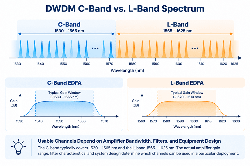
The conventional C-band is commonly described as spanning approximately 1530 to 1565 nm. Extended C-band systems can reach roughly 1528 to 1568 nm, although the exact boundaries vary by equipment design.
The L-band extends to longer wavelengths, commonly described as approximately 1565 to 1625 nm. These nominal band definitions do not mean that every wavelength in the range is usable in every optical system.
Amplifier gain windows are narrower than some nominal band definitions. A C-band EDFA typically covers approximately 1530 to 1565 nm, while an L-band EDFA may cover a range such as 1570 to 1610 nm. Actual operating windows depend on the amplifier model. Channels outside the supported gain range may not receive sufficient amplification.
At 100 GHz spacing, a conventional C-band plan commonly accommodates around 40 channels. At 50 GHz spacing, a comparable plan may accommodate around 80. Extended C-band designs can support additional channels, including specific 96-channel configurations at 50 GHz spacing.
The usable L-band channel count is implementation-dependent. It depends on the actual amplifier bandwidth, filter characteristics, channel spacing, and the manufacturer’s supported channel plan. Consequently, there is no universal 40-channel or 80-channel limit that applies to every L-band deployment.
Some 96-channel, 50 GHz MUX/DEMUX products use the C15–C62 designation. Because these labels are manufacturer-specific, the exact frequency assignments and first and last channel positions must be confirmed against the product channel map.
The IEEE 802.3ct/100GBASE-ZR application example also illustrates why a standards-defined channel plan should not be confused with a universal band definition. Its 48-channel, 100 GHz grid is a defined application range rather than a rule governing every DWDM system.
Not every nominal grid position is necessarily usable in a real network. Band edges, guard bands, amplifier gain bandwidth, filter passbands, and vendor-specific channel maps can all reduce the number of channels available for a particular deployment. A 40-channel MUX may provide 40 ports, but the end-to-end design must still meet the required optical performance for every assigned channel.
How Many DWDM Channels Does One Fiber Carry?
Short answer, by common design:
- About 40 channels in the C-band at 100 GHz spacing
- About 80 channels in the C-band at 50 GHz spacing
- About 80 channels across C-band and L-band at 100 GHz
- About 160 channels across C-band and L-band at 50 GHz
- More than that with a flex grid, depending on baud rate and reach
| Band | Wavelength Range | 100 GHz Count | 50 GHz Count | Amplifier | Typical Use |
| C-band | 1530–1565 nm | ~40 | ~80 | C-band EDFA | Metro, regional, DCI |
| L-band | 1565–1625 nm | ~40 | ~80 | L-band EDFA | C-band exhaust, long haul |
| C + L | 1530–1625 nm | ~80 | ~160 | Dual-band | High-capacity corridors |
Many deployments start with the C-band because its components and operating practices are widely established. L-band can provide additional capacity when demand justifies the extra amplifiers, filters, and operational complexity.
The decision should be based on the supported gain spectrum, required channel count, link budget, and cost of the complete optical system rather than a fixed assumption that every C+L deployment provides a specific number of additional channels.
How to Build a DWDM Channel Plan
A DWDM channel plan is the documented assignment of frequencies and wavelengths to services, ports, nodes, and directions. The grid tells you what’s possible. The plan tells you what’s actually in use.
Here’s the workflow we recommend:
1. Inventory services, rates, and direction. List every circuit, its bit rate, and whether it needs a protected path. Decide between dual-fiber and single-fiber operation early.
2. Choose the band. Start with C-band. Add L-band only when the C-band plan is exhausted or nearly so.
3. Choose the grid. Use 100 GHz for legacy optics and simpler links. Use 50 GHz when density or coherent optics justify the tighter tolerances.
4. Allocate with headroom. Reserve roughly 20% of channels for growth. Keep guard channels at the band edges rather than lighting the first and last slots.
5. Match the optics. Fixed or tunable, 100 GHz or 50 GHz, C-band or L-band. Every combination has to match the plan. Our fixed and tunable DWDM transceiver guide explains the main selection considerations.
6. Match the mux, OADM, and filters. Confirm port passbands and calculate insertion loss for the whole path, not just one node.
7. Verify the link budget, then document and audit. Check OSNR and receiver sensitivity before cutover. Update the plan the same day a circuit changes.
Worked Example: A 40-Channel C21–C60 Plan
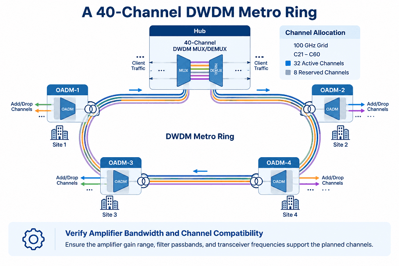
Consider a metro ring with a hub and four OADM sites. The team selects a 100 GHz grid and a C21–C60 plan, providing 40 nominal channel center frequencies from 192.1 to 196.0 THz, corresponding to wavelengths from approximately 1560.61 to 1529.55 nm.
C60 sits slightly below the conventional 1530 nm C-band boundary. Before finalizing the design, the team must confirm that the selected amplifier’s gain window and all relevant optical components support this channel.
The team activates 32 channels on day one and reserves eight for future growth. At the hub, it uses a 40-channel low-insertion-loss DWDM MUX/DEMUX specified at no more than 3.5 dB insertion loss per device. The end-to-end link budget must account for both the transmitting MUX and receiving DEMUX, along with the remaining path losses.
The spoke sites drop only the channels required by their connected services.
For spares, the team stocks a small number of fixed-wavelength optics and one 10G DWDM tunable SFP+. The tunable module can cover multiple channel assignments within its supported tuning range, reducing the number of fixed-wavelength SKUs required in inventory. Its full frequency range and host compatibility must be verified before relying on it as a universal spare.
When more capacity is needed, one possible upgrade path is a 96-channel, 50 GHz MUX/DEMUX using the manufacturer’s C15–C62 channel plan. This can provide a denser channel arrangement, but it is not simply a port-count upgrade. The team must review the exact channel map, transceiver compatibility, filter passbands, amplifier range, and end-to-end link budget before migration.
Channel-Plan Bookkeeping
A plan only works if people can read it six months later. At minimum, record:
- Channel label and frequency
- Wavelength and band
- Grid and spacing
- TX and RX direction
- Node A and node B
- Mux or OADM port
- Service name and rate
- Status and owner
Consider an illustrative planning scenario. A metro carrier’s transport planner, Denise, finds an apparently free C21 in the master spreadsheet. Two days before cutover, an audit of the live inventory reveals that C21 is already carrying a 10G backup circuit between two hubs over the same shared optical span. The spreadsheet has not been updated for three months.
The new service is reassigned to C34 at 193.4 THz, and the cutover proceeds without a channel conflict. Without the audit, assigning both services to the same frequency on the shared span could have caused an optical channel collision.
The lesson is not merely to choose a free channel. It is to verify that the channel is actually available on the specific optical path and to keep the plan synchronized with the live network.
Common DWDM Channel Mistakes
Most channel-planning problems can be avoided by checking frequency assignments, component compatibility, and the complete optical path. Common mistakes include:
- Configuring by channel label alone. Verify the nominal center frequency, especially when using tunable optics or equipment from different vendors.
- Assuming 50 GHz and 100 GHz equipment is automatically compatible or incompatible. Check frequency alignment, signal bandwidth, and filter passbands before combining components.
- Assuming every nominal grid position is usable. Band edges, amplifier gain windows, guard bands, and filter characteristics may restrict the available channels.
- Failing to reserve capacity for growth. A fully occupied channel plan can force an expensive upgrade when new services arrive.
- Mixing C-band and L-band equipment without checking the design. Amplifier windows, filters, and supported frequency ranges must match the selected channels.
- Allowing the channel plan to become outdated. Unrecorded adds, moves, and changes can create duplicate assignments and service interruptions.
- Blaming the channel before checking the connector. A contaminated or damaged LC end face can introduce significant optical loss and make a healthy channel appear faulty. Inspect and clean connectors before replacing hardware unnecessarily.
Our DWDM equipment overview covers the roles of MUX/DEMUX units, OADMs, and optical amplifiers in a DWDM system.
FAQ
What is a DWDM channel?
A DWDM channel is an optical signal centered at a nominal frequency on the DWDM grid. Its center frequency is defined by the channel plan, while its usable spectrum depends on the signal bandwidth and the optical components along the link.
How many channels does DWDM support?
A conventional C-band plan commonly supports about 40 channels at 100 GHz spacing or about 80 at 50 GHz spacing. Extended C-band and C+L systems can support more, depending on the equipment and usable spectrum. Flex-grid allows flexible spectrum allocation rather than guaranteeing a fixed channel count.
How many channels are in C-band DWDM?
A conventional C-band deployment commonly provides around 40 channels at 100 GHz spacing or around 80 at 50 GHz spacing. Extended C-band equipment may support additional channels. The actual count depends on the supported frequency range, filter design, and vendor channel map.
What is the difference between 50 GHz and 100 GHz DWDM?
The difference is the frequency separation between adjacent nominal channel center frequencies. A 50 GHz grid provides closer channel spacing and can support greater channel density in a comparable spectrum, but it places tighter requirements on optical frequency alignment, signal bandwidth, and filtering. A 100 GHz grid provides wider separation and may be more suitable for existing equipment or simpler link designs.
What is DWDM channel 21?
In the common 100 GHz C21–C60 plan used in this guide, C21 corresponds to 192.1 THz, or approximately 1560.61 nm. A different vendor’s channel numbering convention may assign a different frequency to a similar label. Always verify the channel map.
Why do different vendors number channels differently?
Channel labels are vendor- or application-specific naming conventions. Vendors may use different starting points, channel ranges, and band-edge rules. The nominal optical frequency is the more reliable reference when checking compatibility between platforms.
What is the ITU-T G.694.1 grid?
ITU-T G.694.1 defines the DWDM spectral frequency grid, including the 193.1 THz reference frequency, fixed channel spacings, and the flex-grid option. It provides the frequency framework used to specify DWDM channel assignments.
Can I use any DWDM channel?
Not necessarily. The ITU grid defines nominal frequency positions, but the usable channels on a particular link depend on transceiver tuning ranges, MUX/DEMUX passbands, amplifier gain bandwidth, link budget, and vendor-supported channel plans.
What is a flex-grid DWDM channel?
A flex-grid DWDM channel uses a frequency slot defined by its nominal center frequency and slot width. The center-frequency granularity is 6.25 GHz, and slot widths are allocated in multiples of 12.5 GHz. This allows spectrum to be assigned according to signal bandwidth and system requirements.
The Channel Number Is a Label. The Frequency Is the Truth.
DWDM channels are defined by their optical frequencies, not by their labels alone. The ITU-T G.694.1 grid provides the frequency reference and spacing, while the selected band determines the available spectrum. Transceivers, filters, amplifiers, and the overall link design determine how many channels can actually be deployed.
A reliable channel plan follows a few basic rules: choose the appropriate band, select 100 GHz or 50 GHz spacing according to the equipment and capacity requirements, reserve room for growth, verify assignments by frequency, and document every change before cutover.
If you’re planning a new DWDM span or upgrading a 100 GHz network to 50 GHz, send us your required channel count, topology, and transmission distance. Our engineers can review the channel plan and identify potential passband, OSNR, link-budget, and compatibility risks before you purchase the equipment.
Contact FiberMall for a channel-plan review and quotation.
The grid provides the framework. A well-maintained channel plan keeps the network aligned as it grows.
Related Products:
-
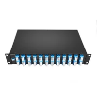
 DWDM MUX DEMUX 50GHZ 96CH (C15-C62) LC/UPC Dual Fiber 2U Rack
$6000.00
-
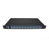
DWDM MUX DEMUX 40CH (C21-C60) LC/UPC Dual Fiber 1U Rack
$1100.00
-
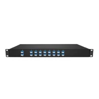
DWDM MUX DEMUX 16CH (C21-C36) with Monitor Port LC/UPC Dual Fiber 1U Rack
$800.00
-
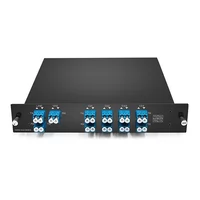
DWDM MUX DEMUX 8CH (C21-C28) with Express Port LC/UPC Dual Fiber LGX BOX
$500.00
-
DWDM MUX 8CH 16 Wavlengths (TX: C43/C45/C47/C49/C51/C53/C55/C57 RX: C44/C46/C48/C50/C52/C54/C56/C58) with MON Port LC/UPC Single Fiber LGX BOX
$450.00
-
SFP-DW10G17-40C 10G DWDM SFP+ C17 100GHz 1563.86nm 40km LC SMF DDM Transceiver Module
$155.00
-
SFP-DW10G17-80C 10G DWDM SFP+ C17 100GHz 1563.86nm 80km LC SMF DDM Transceiver Module
$175.00
-
SFP-DW10G17-100C 10G DWDM SFP+ C17 100GHz 1563.86nm 100km LC SMF DDM Transceiver Module
$235.00
-
SFP-DW10GTU-40C 10G DWDM Tunable SFP+ 50GHz 1529.55nm~1561.83nm 40km LC SMF DDM Transceiver Module
$550.00
-
SFP-DW10GTU-80C 10G DWDM Tunable SFP+ 50GHz 1529.55nm~1561.83nm 80km LC SMF DDM Transceiver Module
$750.00
-
OSFP-400G-DCO-ZR 400G Coherent OSFP-DCO ZR C-band Tunable Optical Transceiver Module
$7000.00
-
OSFP-400G-DCO-ZR+ 400G Coherent OSFP-DCO ZR+ C-band Tunable Optical Transceiver Module
$7000.00
-
OSFP-800G-DCO-ZR+-HTx 800G Coherent High TX Power OSFP DCO ZR+ C-band Tunable Optical Transceiver Module
$12000.00
-
OSFP-800G-DCO-ZR-HTx 800G Coherent High TX Power OSFP DCO ZR C-band Tunable Optical Transceiver Module
$11000.00
-
QSFP-DD-400G-DCO-ZR 400G Coherent QSFP-DD DCO C-band Tunable Optical Transceiver Module
$4550.00
-
QSFP-DD-400G-DCO-ZR+ 400G Coherent QSFP-DD DCO C-band Tunable Optical Transceiver Module
$4680.00
-
QSFP-DD-400G-DCO-ZR+-HTx 400G Coherent High TX Power QSFP-DD DCO OpenZR+ C-band Tunable Optical Transceiver Module
$5500.00
-
QSFP-DD-400G-DCO-ZR-HTx 400G Coherent High TX Power QSFP-DD DCO ZR C-band Tunable Optical Transceiver Module
$5200.00