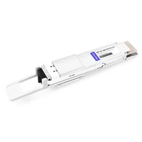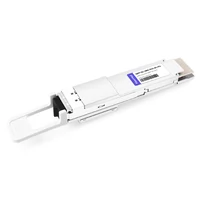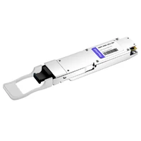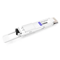

400G ZR+ coherent transceivers are changing how operators build high-capacity optical networks. By integrating coherent signal processing into compact QSFP-DD and OSFP modules, they enable long-distance 400G connectivity directly from compatible switches and routers, reducing dependence on separate optical transport equipment.
But this integration creates a thermal challenge.
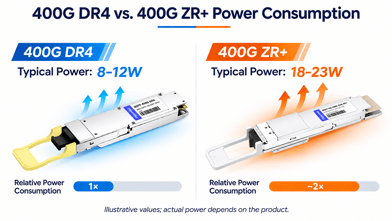
A conventional 400G DR4 transceiver may consume around 8–12W, while many 400G ZR+ coherent modules operate in the 18–23W range. Some high-power implementations can reach approximately 30W. Packing this much processing power into dense front-panel ports increases thermal demands and can affect neighboring modules.
When the surrounding cooling system cannot remove the heat effectively, even a healthy optical link may become unstable.
This article explains why 400G ZR+ transceivers can overheat adjacent ports, how thermal coupling affects network reliability, and what engineers can do to prevent costly failures.
The Failure: Link Flapping Two Weeks After Go-Live
Consider a typical deployment scenario.
A network operator upgrades a metro data center interconnect using 400G ZR+ coherent transceivers installed in a high-density switch. The initial commissioning tests pass. Optical power levels are within specification, the forward error correction (FEC) counters look normal, and traffic flows without interruption.
Two weeks later, intermittent link flapping begins.
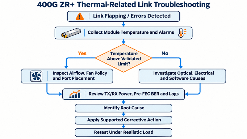
The affected interfaces briefly lose connectivity before recovering automatically. At first, engineers suspect fiber contamination, incompatible firmware, or optical signal degradation.
However, a closer investigation reveals several clues:
- Link instability becomes more frequent during periods of higher ambient temperature or sustained equipment load.
- Module temperature readings increase before some of the failures.
- One or more neighboring transceivers show temperature alarms or elevated error counters.
- Increasing cooling capacity or moving modules to approved alternative ports improves stability.
The problem may not be a defective transceiver. It may be insufficient thermal margin.
A 400G ZR+ module operating within its individual specification can still contribute to a local thermal environment that reduces the margin available to adjacent ports.
This is an illustrative troubleshooting scenario, not a claimed real-world customer incident. Similar symptoms can have electrical, optical, or software causes and require measurement to confirm a thermal root cause.
Why 400G ZR+ Runs So Hot: The Thermal Physics of Coherent Optics
Unlike conventional short-reach optical transceivers, 400G ZR+ modules integrate much of the functionality traditionally provided by dedicated coherent transport equipment.
The additional processing capabilities come with greater electrical power consumption.
A typical digital coherent optics (DCO) module incorporates a high-performance digital signal processor (DSP), high-speed analog-to-digital and digital-to-analog conversion, coherent modulation and detection circuitry, a tunable laser, and FEC processing.
These components enable complex optical signal transmission over metro and regional networks. Depending on the supported modes and optical line system, 400G ZR+ can extend far beyond the approximately 120 km application range associated with standardized 400ZR.
However, nearly all electrical power consumed by these components ultimately becomes heat within the module or its immediate thermal environment.
Heat generation can be estimated from the module’s electrical power consumption:
Heat generation ≈ Electrical power consumed
For example, a 23W coherent module produces approximately 23W of thermal load during steady-state operation.
The challenge is not simply the absolute power consumption. It is the concentration of that power within a small pluggable enclosure, potentially surrounded by other heat-generating devices.
400G DR4 vs. 400G ZR+ at a Glance
| Parameter | 400G DR4 | 400G ZR+ |
| Primary application | Short-reach data center interconnect | Metro, regional, and long-distance coherent transport |
| Transmission technology | Direct detection, PAM4 | Coherent detection, advanced modulation |
| Typical reach category | Up to 500 m for standard DR4 | Hundreds of kilometers to 1,000+ km, depending on system |
| Illustrative power range | Approximately 8–12W | Approximately 18–23W; some high-power variants up to 30W |
| Optical processing | Comparatively simple | Integrated coherent DSP and optical processing |
| Thermal requirements | Lower overall heat load | Higher thermal density and cooling demands |
| Deployment considerations | Standard port compatibility and cooling | High-power port support, airflow, module cooling, and port placement |
Power figures are representative published product specifications, not universal limits. Actual values depend on the module, operating mode, and manufacturer.
Published examples include Cisco’s 12W maximum-power QSFP-DD DR4 module and coherent ZR/ZR+ implementations described in Juniper’s hardware documentation.
The important distinction is that 400G ZR+ places a significantly higher thermal load on the host platform than many standard 400G short-reach optics.
A switch designed to accommodate 400G DR4 modules in every port may not necessarily support a fully populated configuration of higher-power coherent transceivers.
The Failure Mechanism: Micro Hot-Spots and “Thermal Drag-Along”
A dense optical switch is not a collection of thermally isolated transceivers.
Modules share mechanical structures, heatsinks, airflow paths, and neighboring heat sources. As a result, thermal conditions in one port can influence the temperature of surrounding ports.
The term thermal drag-along can be used descriptively for this effect, although it is not a formal industry-standard failure classification.
Two mechanisms are particularly important when investigating thermal-related link instability.
Path 1: Metal Cage Conduction and the Thermal Drag-Along Effect
QSFP-DD and OSFP transceivers are installed in metallic cages that provide mechanical alignment, electromagnetic shielding, and thermal interfaces.
These metal structures can also conduct heat.
When a 400G ZR+ module operates at high power, thermal energy moves from its internal components through the module housing and into the surrounding cooling structures.
Under normal conditions, heatsinks and forced airflow remove sufficient heat to maintain the specified module temperature.
However, several conditions can reduce cooling effectiveness:
High port density: Closely spaced modules increase localized heat generation and reduce available thermal margin.
Restricted airflow: Cable congestion, unsuitable front-panel layouts, blocked inlets, or insufficient fan performance can reduce convective cooling.
Shared thermal structures: Adjacent ports may exchange heat through their cages, supporting metalwork, or heatsink assemblies.
Uneven heat distribution: A high-power coherent module may create a localized hot region that is not reflected by the average chassis temperature.
The resulting effect is straightforward.
A neighboring transceiver can operate at a higher temperature than it would in isolation, even though its own electrical power consumption has not changed.
The consequences depend on the platform and module design. These may include elevated module temperatures, reduced reliability margin, temperature alarms, or protective shutdowns.
Importantly, proximity alone does not prove that one module caused another to fail.
Engineers should compare temperature telemetry, airflow conditions, and port behavior before and after controlled placement changes.
Path 2: EML Thermal Rollover and Optical Power Collapse
Electro-absorption modulated lasers (EMLs) are widely used in certain high-speed direct-detection optical transceivers.
At elevated temperatures, some EML designs can experience reduced modulation performance or optical output efficiency. This behavior is sometimes described as thermal rollover.
However, EML thermal rollover should not be treated as the default failure mechanism in a 400G ZR+ coherent transceiver.
Coherent ZR+ transmitters generally use a tunable laser and coherent I/Q modulation architecture rather than the conventional EML transmitter architecture used in many direct-detection designs.
In coherent modules, excessive temperature can instead affect several temperature-sensitive subsystems, including:
- Tunable laser operating conditions and frequency stability.
- Optical modulation performance and control circuitry.
- DSP and supporting electronic components.
- Internal temperature control and protection mechanisms.
Depending on the specific hardware, firmware, and operating conditions, these effects may reduce optical performance margin or cause the module to enter a protective state.
The visible symptoms can include changes in transmit optical power, degraded signal quality, increased pre-FEC bit error rate (BER), uncorrectable errors, or complete link interruption.
But engineers should avoid assuming that every temperature-related link failure involves a collapse in optical output power.
A more reliable investigation correlates the following measurements:
Module temperature → Optical power and coherent performance metrics → FEC errors → Link events
If optical power remains stable while error rates increase, investigate signal quality, coherent DSP performance, and other optical impairments.
If optical power suddenly disappears, determine whether a temperature alarm, laser shutdown, module reset, or host power event occurred.
The objective is to identify the actual failure mechanism rather than diagnosing from temperature alone.
TCO Reality Check: What the Heat Costs vs. What ZR+ Saves
Thermal performance should be part of the total cost of ownership (TCO) evaluation for every 400G ZR deployment.
Although 400G ZR+ consumes more power than many short-reach optics, the relevant economic comparison is not simply DR4 versus ZR+.
These modules solve different transmission problems.
The more meaningful comparison is between a coherent pluggable deployment and an alternative transport architecture providing equivalent reach, capacity, and reliability.
The CAPEX Win
The primary economic advantage of 400G ZR+ comes from optical transport integration.
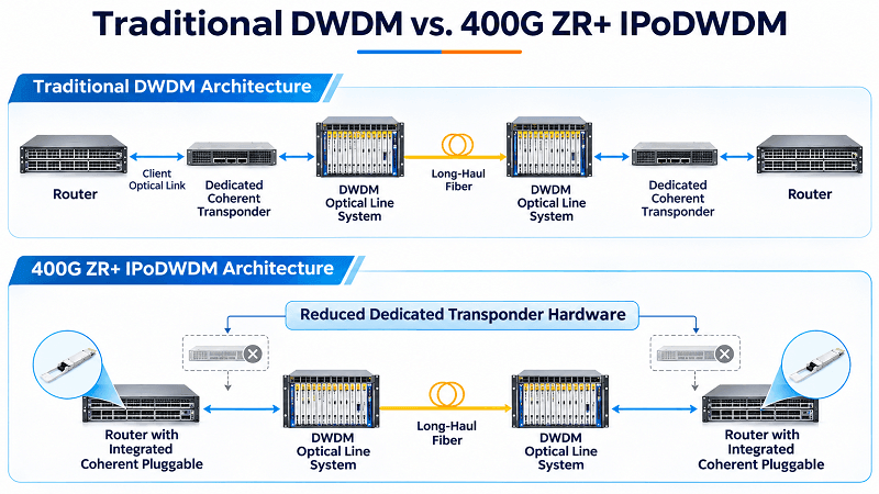
In a traditional architecture, a router may require a separate transponder or muxponder system to convert client traffic into a coherent DWDM signal.
A compatible 400G ZR+ transceiver can perform the necessary coherent transmission functions directly from the router or switch.
This architecture, commonly called IP over DWDM (IPoDWDM) or routed optical networking, can reduce the need for separate transponder hardware.
Potential savings include:
- Fewer dedicated transponder or muxponder cards.
- Reduced chassis and rack-space requirements.
- Fewer intermediate electrical and optical connections.
- Simplified equipment integration and network operations.
- Potentially lower system-level power and cooling requirements.
However, 400G ZR+ does not automatically eliminate the need for optical amplifiers, ROADMs, multiplexers, or other optical line system components.
The required infrastructure depends on distance, fiber characteristics, optical signal-to-noise ratio (OSNR), and network topology.
Therefore, the actual CAPEX benefit must be calculated for the complete network design, not estimated from transceiver pricing alone.
The Downtime Cost
Power consumption is only one part of the operating cost.
Consider an illustrative thermal load comparison:
A 400G DR4 module rated at 12W is replaced in a port planning model by a 400G ZR+ module rated at 23W.
The difference is:
23W − 12W = 11W per port
Across 24 populated ports, the additional thermal load would be:
24 × 11W = 264W
This does not mean that the modules are interchangeable for the same transmission application. It simply illustrates the impact of increased port-level power density.
The additional electrical energy associated with this 264W difference over one year of continuous operation is approximately 2,313 kWh, before accounting for cooling overhead.
At an illustrative electricity price of $0.15/kWh, this represents approximately $347 annually.
The energy cost may be modest relative to the network’s total operating budget.
However, the cost of an unexpected outage can be substantially higher.
Downtime can involve service-level agreement penalties, emergency maintenance, traffic rerouting, lost business activity, and troubleshooting labor.
A more useful TCO model is:
Net TCO Benefit = Avoided Transport Equipment Costs − Additional Module, Power, Cooling, Licensing, and Reliability Costs
The essential lesson is that thermal management is not simply a cooling expense.
It is part of protecting the financial value of the coherent pluggable architecture.
Three Field Rules to Prevent Thermal Hot-Spots
Preventing 400G ZR+ thermal problems starts with validating the entire deployment environment, not just the optical module.
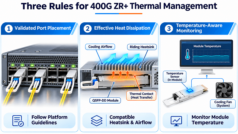
Three practical rules can significantly improve thermal reliability.
Rule 1: Never Mix 400G ZR+ and Standard Modules Slot-to-Slot Without Validation
Installing 400G ZR+ and conventional 400G transceivers next to one another is not universally prohibited.
Some platforms support mixed installations, while others impose strict port placement or population limits for high-power coherent optics.
The correct approach is to follow the switch manufacturer’s documented thermal and power restrictions.
For example, Juniper documents specific 400ZR port limitations on certain QFX platforms. On selected 32-port systems, only 16 designated ports support 400ZR operation, with neighboring positions required to remain unused.
This shows why a physically compatible QSFP-DD interface does not guarantee unrestricted port population.
Before mixing 400G ZR+ and 400G DR4 modules:
- Verify the exact host platform and supported software release.
- Confirm the maximum permitted power per port.
- Review the vendor’s supported coherent module population pattern.
- Check whether adjacent ports must remain unused.
- Validate thermal performance under the intended traffic and ambient conditions.
Where the vendor does not provide clear guidance, use a conservative deployment plan and obtain approval before scaling to a fully populated configuration.
Field principle: Port placement must follow validated thermal support, not assumptions based on connector compatibility.
Rule 2: Use High-Power-Capable Ports, Cages, and Riding Heatsinks
A coherent module’s rated power consumption must be compatible with the host platform’s electrical power delivery and thermal design.
Simply installing a high-power module in a mechanically compatible cage is not sufficient.
For QSFP-DD platforms, effective cooling may involve a riding heatsink that contacts the transceiver housing, a suitable cage structure, and controlled airflow across the module.
Some high-power coherent modules also incorporate extended external heatsink designs, such as QSFP-DD Type 2A constructions.
A riding heatsink can improve heat transfer from the module to the cooling airflow, but its effectiveness depends on contact pressure, surface flatness, airflow, and the system’s overall mechanical design.
An extended module heatsink can also influence front-panel airflow. In poorly matched installations, additional heatsink structures may restrict air intake rather than improve cooling.
Before choosing a host platform, verify:
- Supported transceiver form factor and mechanical design.
- Maximum electrical power allocation for each port.
- Compatibility with the required high-power module type.
- Available heatsink and airflow capacity.
- Supported operating case-temperature range.
- Front-panel clearance and cable-management requirements.
For standard-temperature modules, an operating case-temperature range of 0°C to 70°C is common, although some products specify different limits.
Always use the actual module datasheet and host-platform requirements.
A higher power-class rating alone does not guarantee adequate cooling.
Rule 3: Bind the Fan Policy to Transceiver Case Temperature
A conventional chassis fan policy may rely primarily on inlet air temperature or internal system sensors.
For high-density coherent optics, those measurements may not fully represent localized thermal conditions at individual transceiver ports.
Where supported, thermal management should consider module temperature telemetry, available through management interfaces such as CMIS.
The goal is to respond before the hottest optical module approaches its specified operating limit.
A practical monitoring strategy includes three elements.
First, monitor module temperatures continuously.
Collect module temperature readings and compare them with the applicable limits for each product.
Remember that telemetry may report an internal sensor value rather than a direct external case-temperature measurement. Sensor location and interpretation must be verified.
Second, correlate temperature with optical performance.
Monitor pre-FEC BER, uncorrectable FEC errors, optical transmit and receive power, available coherent signal-quality indicators, and interface events.
Rising temperature alone does not prove an optical problem. Correlated trends provide stronger evidence.
Third, optimize fan control using supported platform features.
If the platform allows transceiver-aware fan policies, use the manufacturer’s recommended configuration and thresholds.
If it does not, follow the prescribed high-power fan profile and establish monitoring alarms through the network management system.
Do not override vendor thermal protection or use unsupported fan-control modifications.
A properly configured cooling system should maintain acceptable module temperatures during sustained load, elevated ambient conditions, and the maximum supported port population.
Quick Reference: 400G ZR+ Deployment De-Risking Checklist
Before placing 400G ZR+ coherent transceivers into production, complete the following checks.
| Checkpoint | What to Verify | Risk Addressed |
| Host compatibility | Exact switch/router model, software release, and supported coherent optics | Unsupported operation |
| Power budget | Maximum module wattage and allowable port power | Electrical or thermal overload |
| Port population | Vendor-approved slot placement and mixing restrictions | Adjacent-port thermal coupling |
| Mechanical cooling | Cage, riding heatsink, module type, and mechanical fit | Poor heat transfer |
| Airflow | Fan configuration, intake clearance, and cable routing | Localized overheating |
| Temperature monitoring | Module telemetry, alarms, and applicable temperature limits | Undetected thermal excursions |
| Optical performance | TX/RX power, pre-FEC BER, FEC errors, and available OSNR indicators | Reduced link margin |
| Stress testing | Maximum supported population under realistic worst-case conditions | Delayed deployment failures |
| Operations readiness | Alarm escalation, firmware versions, and replacement procedures | Extended downtime |
For higher-risk deployments, thermal validation should be performed with the complete intended port population installed.
A single-module bench test may not reveal thermal coupling that appears when several coherent transceivers operate simultaneously.
Engineers should also repeat relevant tests after major software upgrades, fan replacements, or changes to airflow management.
Deployment acceptance criterion: Every installed transceiver must remain within its specified operating limits while the network meets the required optical performance and stability targets.
Conclusion: Port Compatibility Is Not Enough
400G ZR and 400G ZR+ coherent transceivers provide an efficient path toward high-capacity metro, regional, and data center interconnect networks.
By integrating coherent processing into pluggable optics, they can reduce transport equipment complexity and improve deployment flexibility.
But higher integration also means higher thermal density.
Heat from a 400G ZR+ transceiver can influence neighboring ports through shared cooling structures and airflow, particularly in densely populated platforms with limited thermal headroom.
This does not mean mixed transceiver deployments are inherently unsafe.
It means that electrical compatibility, mechanical compatibility, and thermal compatibility must all be validated before deployment.
For network operators, the most effective strategy combines approved high-power port configurations, suitable cooling hardware, transceiver-aware monitoring, and realistic thermal stress testing.
The objective is not simply to keep a 400G ZR+ module running.
It is to ensure that the entire network remains stable, efficient, and reliable as coherent optical density increases.
For engineers planning a 400G ZR deployment, FiberMall can help evaluate coherent transceiver specifications, host compatibility, and application requirements before production rollout.
For a broader introduction to the technology, explore our 400G ZR vs. ZR+ vs. OpenZR+ comparison guide.
Frequently Asked Questions
Can I mix 400G ZR+ and 400G DR4 transceivers in the same switch?
Yes, if the switch platform supports both module types and permits the intended port arrangement. Some platforms restrict high-power coherent transceivers to designated ports or require unused neighboring positions. Always check the manufacturer’s compatibility matrix, power limits, and thermal population guidelines.
How much power does a 400G ZR+ coherent transceiver consume?
Many QSFP-DD 400G ZR+ coherent transceivers consume approximately 18–23W, although certain high-power implementations may reach around 30W. Actual power depends on module architecture, operating mode, manufacturer, and product generation. Always use the specific module’s maximum rated power when planning the host power budget.
What is EML thermal rollover?
EML thermal rollover refers to temperature-related degradation in the optical performance or efficiency of certain electro-absorption modulated laser designs. It may affect some direct-detection transceivers, but it is not the standard transmitter failure mechanism for coherent 400G ZR+ modules, which typically use tunable lasers and coherent I/Q modulators. Coherent thermal faults require separate investigation of laser control, modulation, DSP operation, and protection mechanisms.
Do I need a special cage for 400G ZR+ modules?
Not necessarily a separate cage, but you do need a host platform with validated electrical and thermal support for the specific coherent module. High-power implementations may require suitable riding heatsinks, enhanced airflow, or particular mechanical configurations. Mechanical QSFP-DD compatibility alone does not guarantee that a switch can dissipate the module’s heat.
How much CAPEX does 400G ZR+ save compared to dedicated DWDM transport?
There is no universal savings percentage. 400G ZR+ can reduce CAPEX by eliminating separate transponder or muxponder functions in suitable IPoDWDM architectures. However, the savings depend on network distance, existing optical line systems, port density, equipment licensing, and operating requirements. A valid comparison must evaluate complete network architectures with equivalent transmission capacity and reliability.
Related Products:
-
 QSFP-DD-400G-DCO-ZR+-HTx 400G Coherent High TX Power QSFP-DD DCO OpenZR+ C-band Tunable Optical Transceiver Module
$5500.00
-
QSFP-DD-400G-DCO-ZR-HTx 400G Coherent High TX Power QSFP-DD DCO ZR C-band Tunable Optical Transceiver Module
$5200.00
-
OSFP-400G-DCO-ZR+ 400G Coherent OSFP-DCO ZR+ C-band Tunable Optical Transceiver Module
$7000.00
-
QSFP-DD-400G-DCO-ZR+ 400G Coherent QSFP-DD DCO C-band Tunable Optical Transceiver Module
$4680.00
-
QSFP-DD-400G-DCO-ZR 400G Coherent QSFP-DD DCO C-band Tunable Optical Transceiver Module
$4550.00
-
OSFP-400G-DCO-ZR 400G Coherent OSFP-DCO ZR C-band Tunable Optical Transceiver Module
$7000.00