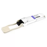
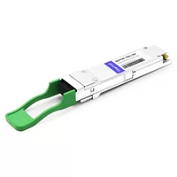
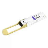
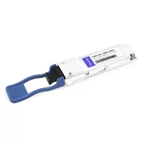
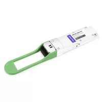
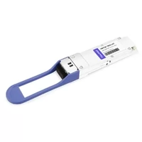
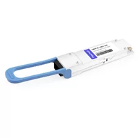
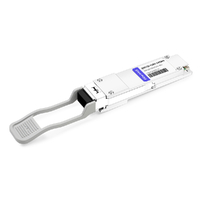
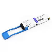
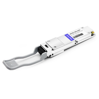
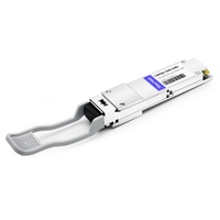
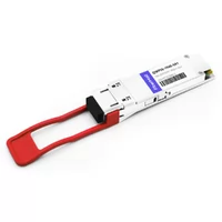
Marcus examined the six QSFP28 LR4 modules arranged on his workbench. He had processed $12,000 worth of RMA’d optics in just two weeks. His 100G spine links kept dropping with CRC errors, and the system showed a frustrating mix of interface flapping and unexplained downtime.
He had verified all fiber runs, executed switch port diagnostics, and cross-tested the cable plant through an exhaustive equipment exchange process. Finally, a senior engineer handed him a $5 fiber cleaning pen and suggested he inspect the duplex LC connector at the far end. One swipe. Problem solved.
Marcus’s story represents an all-too-common scenario in network engineering: connector contamination remains the leading cause of 100G link failures. Beyond physical maintenance, engineers deploying QSFP28 transceivers frequently make expensive architectural mistakes. Selecting the wrong module tier can easily triple deployment costs without delivering any practical benefit. Failing to verify FEC (Forward Error Correction) alignment before deployment guarantees a weekend lost to baseline troubleshooting. Furthermore, inserting an uncoded, third-party module into a locked-down switch platform ensures the port remains completely inactive.
This guide provides the definitive roadmap for selecting, deploying, and troubleshooting QSFP28 transceivers while bypassing the painful trial-and-error phase. Below, you will find comprehensive module comparisons, realistic market pricing, and precise vendor compatibility protocols to ensure a seamless 100G spine-leaf fabric deployment or 40G migration.
If you’re already planning beyond 100G, our QSFP-DD transceiver guide covers 400G and 800G deployment strategies.

What Is QSFP28?
The abbreviation QSFP28 stands for Quad Small Form-factor Pluggable 28. The name breaks down simply: “Quad” means four lanes, “SFP” refers to the Small Form-factor Pluggable mechanical standard “28” indicates each lane runs at 28 Gbps.
Four lanes at 28 Gbps yield a raw throughput of 112 Gbps. However, standard 100G Ethernet signaling relies on 4×25G NRZ (Non-Return-to-Zero) encoding to achieve exactly 100 Gbps of payload capacity. The 28 Gbps physical ceiling provides the necessary overhead for clocking and error-correction protocols. Because each of the four lanes functions independently, a single QSFP28 port can also be broken out into four discrete 25G connections.
The electrical interface uses CAUI-4, which stands for 100 Gigabit Attachment Unit Interface 4-lane. This defines how the switch ASIC talks to the module. CAUI-4 runs at roughly 25.78125 Gbps per lane with 64b/66b encoding. The module converts these four electrical lanes into four optical wavelengths for CWDM4/LR4/ER4 or four parallel fibers for SR4/PSM4.
The main practical point that users must understand is that QSFP28 functions as a physical connector rather than an exact optical technology. The same physical module shell can use multimode VCSELs, single-mode DFB lasers or PAM4 single-lambda optics, depending on the specific variant. The QSFP28 transceiver provides data center operators with deployment flexibility, which enables it to become the most common 100G standard used in present-day data centers.
Key Specifications
| Specification | Value |
| Form Factor | QSFP28 (per SFF-8665) |
| Electrical Interface | CAUI-4 (4×25.78125 Gbps NRZ) |
| Total Bandwidth | 100 Gbps |
| Dimensions | 18.35mm × 8.5mm × 72.4mm |
| Typical Power | 3.5W – 4.5W |
| Max Power MSA Limit | 4.5W (per MSA) |
| Backward Compatibility | QSFP+ (40G) in QSFP28 port |
| Management Interface | CMIS or legacy AVS via I2C |
| Operating Temperature | 0°C to 70°C (Commercial Grade) |
One detail that’s easy to miss: QSFP28 ports accept QSFP+ (40G) modules, but QSFP28 modules won’t work in legacy QSFP+ ports. The electrical signaling is different. The port reduces its capacity to 40G when a QSFP+ module gets inserted, which helps with migration but does not function in reverse.

QSFP28 Module Types Compared
Not all QSFP28 modules are interchangeable. The correct selection requires you to identify your distance needs together with your fiber system and financial resources. The following explanation shows the functions of each available variant.
SR4 is the workhorse for short-reach data center links. 850nm VCSELs operate through parallel multimode fiber (OM3/OM4) which connects with an MPO-12 connector. The system can achieve 100m distance on OM4 and 70m distance on OM3. SR4 provides the most economical solution for connecting equipment located within the same rack or in nearby racks. The device normally consumes 3.5W of electrical power.
LR4 covers long-reach single-mode links up to 10km. The system uses four 25G lanes which it multiplexes onto four CWDM wavelengths (1271nm, 1291nm, 1311nm, 1331nm) over a single duplex LC fiber. LR4 serves as the primary solution for building connections and campus-wide link requirements. The system consumes approximately 4.0W of electrical power.
CWDM4 is the cost-optimized middle ground. The system uses four CWDM wavelengths through duplex LC single-mode fiber to achieve 2km of maximum distance. The shorter specification requires less power from lasers which results in a decrease in production costs. The CWDM4 system provides a 150-200 dollar savings per port when compared to LR4 in data center interconnects where 10km distance requirements exceed actual needs.
PSM4 uses four parallel single-mode fibers with an MPO connector, reaching up to 500m. The technology enjoyed widespread usage until CWDM4 achieved its current level of development. PSM4 requires more expensive single-mode MPO cabling and offers no real advantage over CWDM4 for most deployments.
ER4 and ZR4 extend reach to 30km and 80km respectively, using cooled EML lasers and stronger FEC. These systems exist as telecom systems which DCI applications which do not function as standard data center equipment. Power consumption increases to 4.5W or higher.
Single-lambda modules (DR1, FR1, LR1) represent a newer approach. They transfer data through one 100G PAM4 lane at 1310nm over duplex LC instead of using four 25G data lanes. DR1 reaches 500m, FR1 reaches 2km, and LR1 reaches 10km. The advantage is simplified fiber plant—no wavelength multiplexing—and lower power (around 3.0W). The catch? They are recent products which cost more and do not work on all switch platforms.
Module Type Comparison Table
| Module | Reach | Fiber Type | Connector | Typical Power | Third-Party Price | Best Use Case |
| SR4 | 100m (OM4) | MMF OM3/OM4 | MPO-12 | 3.5W | $120-180 | Intra-DC, adjacent racks |
| CWDM4 | 2km | SMF | Duplex LC | 3.5W | $280-380 | Data center interconnect |
| LR4 | 10km | SMF | Duplex LC | 4.0W | $450-600 | Campus, metro links |
| PSM4 | 500m | SMF | MPO-12 | 3.5W | $300-400 | Legacy SMF parallel (rare) |
| ER4 | 30km | SMF | Duplex LC | 4.5W | $1,200-1,800 | Long-haul DCI |
| ZR4 | 80km | SMF | Duplex LC | 4.5W+ | $2,500-4,000 | Telecom backbone |
| DR1 | 500m | SMF | Duplex LC | 3.0W | $200-280 | Short SMF, low power |
| FR1 | 2km | SMF | Duplex LC | 3.0W | $320-420 | CWDM4 alternative |
| LR1 | 10km | SMF | Duplex LC | 3.5W | $500-650 | LR4 alternative |
How to Choose the Right QSFP28 Module
Engineers systematically over-provision optical links. Specifying LR4 modules for a 300-meter indoor run simply because “it provides extra margin” is an expensive habit. Across a 200-port fabric deployment, that unnecessary margin translates directly into $40,000 of wasted capital. Apply this systematic selection framework:
Step 1: Determine required reach. You must measure your actual fiber distance through physical measurement instead of using straight-line measurement. The fiber runs through the same path as the cable trays, conduits and patch panels. The actual distance between two buildings, which appears as an 800-meter distance on a map, actually measures 1200 meters because you need to trace the real distance. You should include a 20 percent extra capacity.
Step 2: Identify your fiber infrastructure. Do you prefer multimode optical fiber or single-mode optical fiber? If you already have OM4 MPO trunks, then you should choose SR4 unless your distance requirement exceeds 100 meters. The use of CWDM4 or LR4 makes sense for your system because you have single-mode structured cabling. You must verify which connector types your system requires because MPO and LC connectors have different requirements.
Step 3: Calculate link budget. Every fiber link loses power. The transmitter sends out a dBm value, which the receiver requires to function at its minimum dBm value, while all components between those two points which include fiber attenuation and connectors and splices, decrease the total available power budget.
The CWDM4 module demonstrates its output capacity by delivering -6.5 dBm but requires -8.5 dBm for receiver operation. That’s a 2.0 dB budget. Single-mode fiber loses about 0.35 dB/km at 1310nm. The distance of 1.5 kilometers results in a 0.53 dB loss. The two connector pairs produce an approximate 0.5 dB loss. Total loss: ~1.0 dB. Your budget remains intact because you have 1.0 dB extra capacity.
Step 4: Match switch capability. Not all switches support all QSFP28 types. Some older platforms don’t recognize single-lambda modules. ZR4 requires specific firmware updates for proper operation. You should verify your switch specifications from the data sheet before making your purchase.
Step 5: Verify vendor compatibility. This is where most deployments stumble. See the compatibility section below for specifics.
The CWDM4 Cost Savings Story
An operations team at a mid-size cloud provider was speccing LR4 for all 100G interconnects—about 340 ports across three data centers. The average run length extended for 800 meters. A network architect pointed out that CWDM4 covers 2km, and every port satisfied the requirement because it operated below that distance. The switch saved $58,000 in optics costs with zero performance impact. The LR4 modules, they didn’t buy? Those would have been complete overkill.
QSFP28 Pricing & Cost Factors
Most vendors hide pricing behind “contact us” buttons. Here’s what QSFP28 modules actually cost in 2026.
Third-party compatible modules from manufacturers like FiberMall typically cost 70-90% less than OEM-branded equivalents. The hardware is often identical because many third-party suppliers use the same ODM sources as the major brands. The difference between the two products exists because one uses EEPROM coding and the other provides warranty support.
Pricing Comparison Table (2026)
| Module Type | Third-Party Price | OEM Price (Cisco/Arista) | Savings |
| SR4 | $120-180 | $800-1,200 | 80-85% |
| CWDM4 | $280-380 | $1,500-2,200 | 75-82% |
| LR4 | $450-600 | $2,000-3,000 | 70-80% |
| ER4 | $1,200-1,800 | $5,000-7,500 | 70-76% |
| ZR4 | $2,500-4,000 | $10,000-15,000 | 70-75% |
| Single-lambda (FR1) | $320-420 | $1,800-2,500 | 78-83% |
Volume discounts kick in at predictable tiers. Most suppliers offer 5-10% off at 50 units, 12-18% at 200 units, and 20-30% at 1,000+ units. DAC and AOC cables follow similar curves.
DAC cables are the budget champion for short reaches. A 1-meter QSFP28 DAC costs 25−40.A3−meterAOCruns25−40.A3−meterAOCruns80-120. Compare that to even an SR28 module pair plus fiber, which starts around $300. For rack-internal connections, DACs are almost always the right call.
QSFP28 Compatibility by Vendor
Switch platforms treat third-party optics differently. Some are permissive. Others are aggressively locked down.
Cisco Nexus 9000 and Catalyst 9000 accept third-party QSFP28 modules, but you must disable DOM threshold checking and manually set port speed to use these modules. The hidden command service unsupported-transceiver (yes, that’s actually the command name) is required on some platforms. The command must be executed because the switch needs it to link up with the transceiver.
The Arista 7000 series stands as the most accessible major platform for third-party vendor integration. Arista’s philosophy states that all modules which comply with MSA specifications will function properly. The system requires no undisclosed commands and no proprietary vendor ties. The switches determine the correct configuration through EEPROM reading. This is why Arista dominates in environments that mix switch and optics vendors.
The Juniper QFX series generally permits third-party module usage, but it demands specific EEPROM revision requirements for certain modules. The QFX switches need CMIS 4.0 or newer versions to enable single-lambda functionality. Juniper’s documentation on this is fragmented, so test before you deploy at scale.
The ecosystem of NVIDIA/Mellanox ConnectX and Spectrum stands as the most restrictive system. The company employs encrypted EEPROM signatures for its products. The system will fail to establish 100G connections through third-party modules that lack NVIDIA-approved programming. The system will recognize the module’s existence yet the connection remains inactive. The solution requires you to use NVIDIA modules, which include MMA1B00-CS4 for SR4 and MMA1L30-CM for LR4 or to partner with a coding house that possesses NVIDIA encryption keys. The platform lock-in requires 3-5 times the expenses of using open platforms.
SONiC and white-box switches running open-source NOS typically accept any MSA-compliant module. The system depends on the development status of its drivers. Some white-box platforms lack proper DDM parsing for newer single-lambda modules. Community forums serve as the most effective debugging resource for this situation.
Vendor Compatibility Matrix
| Platform | QSFP28 Support | Third-Party Friendly | Notes |
| Cisco Nexus 9000 | Full | Yes (with commands) | service unsupported-transceiver required |
| Arista 7000 | Full | Yes | Most permissive major vendor |
| Juniper QFX | Full | Mostly | Check CMIS version for single-lambda |
| NVIDIA Spectrum | Full | No | Encrypted EEPROM required |
| Dell Z-Series | Full | Yes | Similar to white-box behavior |
| SONiC/White-box | Full | Yes | Driver maturity varies |
For platform-specific CLI commands and detailed coding requirements, see our QSFP28 compatibility guide.
QSFP28 Cabling Options
Your cabling choice is as important as your module choice. Making an incorrect selection will result in three problems, which include insertion loss, compatibility issues and polarity headaches.
DAC (Direct Attach Copper) uses passive copper twinax cable with integrated QSFP28 connectors on each end. The system consists of copper traces without any optical components or active parts. The system achieves extremely low power consumption through its design, which results in DACs costing between $25 and $40 for 1m in length. The trade-off is reach: 1-3 meters typical, 5 meters max for passive. Active DACs extend to 7-10 meters but cost more and use slightly more power.
DACs serve as the connection solution between switches and servers which operate within a single rack space. The system serves as the standard connection method between Top-of-Rack and server links which operate at 100G.

The AOC (Active Optical Cable) system connects its optical engines through optical connectors which transmit data through fiber links between these connectors. The AOC functions as a permanent connection between two modules through a fiber optic cable. The maximum distance between two points reaches 100 meters. Each endpoint consumes power in the range of 1 to 2 watts. The cost for short lengths starts at 80 to 120 but reaches 300 after 100 meters.
AOCs provide better performance than DACs because they extend distance requirements without needing users to operate distinct modules and fiber jumpers. The high-density racks use this technology because it solves their cable management needs.
The structured fiber system provides users with complete design independence. You buy separate QSFP28 modules and fiber cables. For SR4, that’s MPO-12 trunk cables. For LR4/CWDM4/ER4, that’s duplex LC single-mode jumpers. Structured fiber costs more upfront but lets you swap module types without replacing cables.
Breakout cables split one 100G QSFP28 port into four 25G SFP28 ports. A QSFP28-to-4×SFP28 breakout DAC costs $60-90 and reaches 1-3 meters. Breakout AOCs reach up to 30m. The wiring uses specific lane mapping: QSFP28 lanes 0-3 map to SFP28 ports 1-4.
Polarity matters with breakout cables. Method B polarity is standard for most data centers. Method C reverses the fiber pairs and causes partial lane failures if both ends don’t match. Always verify your cable polarity against your patch panel documentation.
Cabling Comparison Table
| Cable Type | Max Length | Power (per end) | Cost (1m) | Best Use Case |
| Passive DAC | 3m | <0.5W | $25-40 | Intra-rack, ToR to server |
| Active DAC | 7m | ~1.0W | $50-80 | Adjacent racks |
| AOC | 100m | ~1.5W | $80-120 | Within row, cable management critical |
| Structured MMF (SR4) | 100m | Module power only | $15-25 (cable) | Flexible infrastructure |
| Structured SMF (LR4) | 10km | Module power only | $10-15 (cable) | Long reach, flexible |
| Breakout DAC | 3m | <0.5W | $60-90 | 100G to 4×25G server |
| Breakout AOC | 30m | ~1.5W | $150-200 | 100G to 4×25G across row |
For more on cable selection in next-generation networks, our QSFP-DD cable compatibility guide covers similar principles for 400G deployments.
QSFP28 Power & Thermal Management
The power consumption of QSFP28 modules operates between 3.5W and 4.5W, while CFP modules require 24W or higher for operation. The 32-port 1RU switch generates more than 140W of heat through its optical components. The power consumption of modules differs according to their specific type. The SR4 and CWDM4 modules consume 3.5W while the LR4 module consumes about 4.0W. The ER4 and ZR4 modules reach 4.5W through their utilization of cooled laser technology. The single-lambda PAM4 modules achieve the highest energy efficiency with their 3.0W power consumption.
The process of thermal planning at the rack level becomes more challenging. Most 1RU switches with 32+ QSFP28 ports use front-to-back or back-to-front airflow. The upper rows of ports run 10-15°C hotter than the lower rows because heat rises and gets trapped. The top four ports of the system operate at temperatures close to their 70°C threshold, while identical modules in the bottom row sit at 45°C.
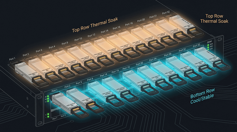
The belly-to-belly cage configuration creates an intensified problem because switches mount directly above each other in adjacent racks. The lower switch exhaust directs air into the upper switch intake. The belly-to-belly configuration requires you to either budget extra thermal headroom or choose shorter cable types that produce lower heat emissions.
DDM (Digital Diagnostic Monitoring) functions as your primary early detection system. The majority of QSFP28 modules transmit their actual temperature and voltage, and transmit power and receive power values. The system establishes two limits. You need to evaluate the airflow system when the module temperature increases by 15 degrees Celsius above its normal operating level. You should examine the connector when receive power decreases to 3dB below the expected level.
Power & Thermal Specifications Table
| Module | Typical Power | Max Power | Thermal Notes |
| SR4 | 3.5W | 4.0W | VCSELs run cool; minimal concern |
| CWDM4 | 3.5W | 4.0W | DFB lasers; moderate heat |
| LR4 | 4.0W | 4.5W | Cooled lasers; watch top-row ports |
| ER4/ZR4 | 4.5W | 5.0W | Cooled EML; plan for extra thermal margin |
| Single-lambda (FR1/LR1) | 3.0W | 3.5W | PAM4 DSP; most efficient option |
For detailed thermal planning methodologies that scale to higher-density form factors, see our QSFP-DD power and thermal guide.
Deploying QSFP28: Best Practices
Getting the hardware right is only half the battle. Configuration and process mistakes cause more outages than defective modules.
Pre-deployment verification checklist:
- Verify switch firmware supports your specific module type
- Check that FEC settings match on both ends (mandatory for fiber)
- Confirm fiber type and connector match the module spec
- Inspect and clean all connectors before insertion
- Document expected DDM values for baseline comparison
FEC configuration is non-negotiable. 100G fiber links require RS-FEC (Reed-Solomon Forward Error Correction). Without it, bit error rates climb to unacceptable levels. The IEEE 802.3bj standard mandates RS-FEC for 100GBASE-SR4, LR4, and ER4.
The FEC Mismatch Weekend
The engineers at the financial services company spent their Saturday work hours investigating what they believed to be a defective fiber installation. The 100G LR4 link, which connected the two trading floors, showed intermittent operation, which included a period of total shutdown before it resumed functioning. The team executed module replacement procedures. The team conducted an OTDR test on the fiber. They examined each cable connection point at the patch panel.
The access switch showed RS-FEC activation status, while the aggregation switch showed no activation of this feature. One end of the system performed error correction functions, but the other end lacked any ability to identify errors. The link established a connection, but it showed two different error rates, which caused it to lose connection. The issue was resolved through a single correct command. The team required only thirty seconds to complete configuration work, while they spent two days investigating operational problems.
Don’t be those engineers. Verify FEC on both ends before you declare a link operational.
The process of cleaning connectors appears simple, but it results in $12000 expenses because of unneeded return material authorizations. Use a dry cleaning pen for LC connectors. The MPO cleaning tool provides specialized cleaning because it cleans all 12 fibers at once. The use of alcohol on angled polish APC connectors is prohibited because it creates residue that harms connector performance.
DDM monitoring setup should be automated. Most NMS platforms can poll DDM via SNMP. Set alerts for:
- Temperature >65°C
- Tx/Rx power deviation >3dB from baseline
- Voltage outside 3.1V-3.5V range
Troubleshooting Common QSFP28 Issues
When a 100G link fails, follow a systematic approach. Random component swapping wastes time and money.
The link fails to load. The physical layer needs examination. The system needs to verify whether it can detect the module. Run show interface transceiver (or your platform’s equivalent). The module detection fails because the system has locked the vendor or the module has malfunctioned. The system detects the module, yet no light appears, so you must verify fiber continuity using a visual fault locator. The system detects light, yet there is no link, so you must verify speed configuration through QSFP28, which requires manual 100G speed configuration instead of using auto-negotiation.
The system experiences intermittent flapping. The problem occurs because of a pattern that leads to false, unfixable issues. FEC settings need to be checked before proceeding with the next step. The next step requires checking fiber integrity since micro-bends in single-mode fiber create errors at regular intervals. The final step involves confirming the current temperature. The system experiences periodic module dropouts when its modules reach their thermal limit.
The system fails to detect the module. The module will not establish a connection when third-party optics are used on a locked platform according to NVIDIA requirements. The system inventory will show the module as present yet it will not establish a connection. You need to check the EEPROM vendor codes. The system displays “unsupported transceiver” logs for certain switches even when the module maintains full electrical compatibility.
The system experiences breakout lane failures. The system shows three active lanes because of a polarity mismatch or a defective breakout cable. The system shows one active lane because of a defective SFP28 port or cable. You need to test each port through systematic swapping until you achieve successful isolation.

Troubleshooting Quick Reference Table
| Symptom | Most Likely Cause | Quick Fix |
| No link, module detected | Dirty connector or wrong fiber type | Clean connectors; verify MMF vs SMF |
| No link, module not detected | Vendor lock or unsupported module | Check compatibility matrix; verify coding |
| Intermittent flapping | FEC mismatch or thermal issue | Match FEC both ends; check airflow |
| High CRC errors | Dirty connector or bend radius violation | Clean and inspect fiber; check bend radius |
| Breakout: 3 of 4 lanes up | Polarity mismatch (Method B vs C) | Verify cable polarity documentation |
| Breakout: 1 of 4 lanes down | Bad SFP28 port or cable | Swap cable to isolate |
| Link up but poor performance | Missing FEC or speed mismatch | Enable RS-FEC; set speed manually |
For a deeper dive on troubleshooting methodology, see our QSFP-DD troubleshooting guide—many of the same principles apply to 100G links.
Migrating from 10G/40G to 100G QSFP28
Most 100G deployments aren’t greenfield. They’re upgrades from existing 10G or 40G infrastructure.
When to upgrade. The economic trigger usually comes from port exhaustion or bandwidth saturation. If your 10G access switches are running at 80%+ utilization during peak hours, it’s time. If you’re buying new switch hardware anyway, 100G QSFP28 is the default choice—it’s barely more expensive than 40G was two years ago.
Phased approach. You don’t need to rip everything out overnight. Most organizations follow this sequence:
- Upgrade core and spine layers to 100G first. These carry the most traffic and benefit most from bandwidth increases.
- Keep 10G/25G at the access layer. Use QSFP28 breakout cables to maintain 25G server connectivity.
- Upgrade access switches to 100G as servers refresh or as bandwidth demands grow.
Your current cabling system will remain intact through this solution. The QSFP28 port, which accepts a QSFP+ 40G module, enables you to reuse optical components during your transition period.
The existing infrastructure will be maintained. The SR4 standard directly utilizes OM4 multimode trunks that you have already installed. The CWDM4 and LR4 systems operate with your existing single-mode structured cabling. The main infrastructure change is MPO vs. LC connector density—MPO-12 trunks pack more fibers in less space but require different patch panels.
The path to 400G. 100G doesn’t represent the final destination. The QSFP-DD switches allow you to use your current QSFP28 modules when you need to switch to 400G. The system provides you with backward compatibility that benefits your operations. Your initial investments go toward upgrading switches while you postpone optics upgrades into future budget periods.
Our QSFP-DD vs QSFP28 vs OSFP comparison breaks down exactly when to make the jump to 400G.
FAQ
Can QSFP28 work in a QSFP+ port?
The ports that QSFPA28 modules need to operate work together with CAUI-4 electrical signaling. QSFP+ ports only support 4×10G. However, the reverse works: QSFP+ modules function in QSFP28 ports at 40G.
What is the difference between QSFP28 and QSFP56?
The 100G output of QSFP28 works through 4×25G NRZ lanes. The 200G output of QSFP56 works through 4×50G PAM4 lanes. The physical design of QSFP56 remains unchanged while its electrical signaling system operates differently. A QSFP56 port can usually accept QSFP28 modules at 100G.
How far can QSFP28 SR4 reach?
The maximum distance for OM4 multimode fiber reaches 100 meters while OM3 fiber supports a maximum distance of 70 meters. The multimode transmission requires single-mode components such as CWDM4 and LR4 to reach extended distances.
Can I use third-party QSFP28 in Cisco switches?
Yes, with caveats. Most Cisco platforms require the service unsupported-transceiver command. Some newer Catalyst switches are more restrictive. Always test one module before ordering in volume.
Does QSFP28 support breakout to 4×25G?
Yes. Use QSFP28-to-4×SFP28 breakout cables (DAC or AOC). The QSFP28 port must support breakout mode, which most modern switches do. Check your switch documentation for specific port group restrictions.
What is the power consumption of QSFP28 LR4?
Typically 4.0W, with a maximum of 4.5W under worst-case conditions. This is well within the power budget of standard QSFP28 cages.
Conclusion
QSFP28 transceivers serve as the critical foundational bedrock driving modern high-speed 100G networking infrastructures. Executing seamless enterprise-scale rollouts relies entirely on enforcing a few uncompromising engineering principles:
- Align Module Specifications Directly to Physical Distance: Stop defaulting to long-reach LR4 optics. Standard CWDM4 hardware reliably clears 90% of normal enterprise Data Center Interconnects at a fraction of the capital expenditure baseline.
- Audit Host Vendor Compatibility Logic Before Procurement: Vendor lock-out loops are real. NVIDIA hardware mandates verified cryptographic keys, Cisco interfaces require hidden command flags, while Arista systems accept standard MSA modules out of the box.
- Enforce Host RS-FEC Alignment Across Both Endpoints: Always execute clean FEC validation passes. Leaving the framing structures asymmetrical guarantees an immediate, continuous link flapping.
- Sanitize Physical Interfaces Before Chassis Insertion: Clean optical facets first. Executing basic wet-dry sweeps prevents unneeded module RMAs.
- Calculate Precise Chassis Thermal Budgets: Packing 32 dense front-facing ports operating at 4.0W each concentrates real heat loads inside compact 1RU chassis spaces. Plan rack cooling configurations accordingly.
Reaching 100G operational capacity represents a vital step along the modern networking continuum. When application architectures demand scaling past baseline QSFP28 limitations, advanced QSFP-DD transceivers provide clear hardware migration vectors out to 400G and 800G throughputs without requiring expensive underlying switch chassis replacements.
Need fully qualified, plug-and-play QSFP28 transceivers? FiberMall delivers precision-coded QSFP28 SR4, CWDM4, LR4, and cutting-edge single-lambda modules pre-validated for flawless deployment across Cisco, Arista, Juniper, and white-box hardware platforms. Reach out directly to our technical engineering group to initiate a comprehensive compatibility analysis for your upcoming network deployment.
Related Products:
-
 QSFP28-100G-SR4 100G QSFP28 SR4 850nm 100m MTP/MPO MMF DDM Transceiver Module
$40.00
QSFP28-100G-SR4 100G QSFP28 SR4 850nm 100m MTP/MPO MMF DDM Transceiver Module
$40.00
-
QSFP28-100G-IR4 100G QSFP28 IR4 1310nm (CWDM4) 2km LC SMF DDM Transceiver Module
$110.00
-
QSFP28-100G-DR1 100G QSFP28 Single Lambda DR 1310nm 500m LC SMF with FEC DDM Optical Transceiver
$180.00
-
QSFP28-100G-PSM4 100G QSFP28 PSM4 1310nm 500m MTP/MPO SMF DDM Transceiver Module
$180.00
-
QSFP28-100G-FR1 100G QSFP28 Single Lambda FR 1310nm 2km LC SMF with FEC DDM Optical Transceiver
$215.00
-
Arista Networks QSFP-100G-LRL4 Compatible 100G QSFP28 LRL4 1310nm (LWDM4) 2km LC SMF DDM Transceiver Module
$245.00
-
QSFP28-100G-LR1 100G QSFP28 Single Lambda LR 1310nm 10km LC SMF with FEC DDM Optical Transceiver
$265.00
-
QSFP28-100G-SR1.2 Single Rate 100G QSFP28 BIDI 850nm & 900nm 100m LC MMF DDM Optical Transceiver
$280.00
-
QSFP28-100G-LR4 100G QSFP28 LR4 1310nm (LAN WDM) 10km LC SMF DDM Transceiver Module
$285.00
-
QSFP28-100G-SWDM4 100G QSFP28 SWDM4 850nm-940nm 100m LC MMF DDM Optical Transceiver
$300.00
-
QSFP28-100G-LR4-20 100G QSFP28 LR4 1310nm LWDM4 20km LC SMF DDM Transceiver Module
$300.00
-
QSFP28-100G-BDRX 100G QSFP28 BIDI 850nm & 900nm Only Receiver 100m LC MMF Optical Transceiver
$379.00
-
QSFP28-100G-SRBD Dual Rate 40G/100G QSFP28 BIDI 850nm & 900nm 100m LC MMF DDM Optical Transceiver
$449.00
-
QSFP28-100G-ER1 100G QSFP28 ER1 Single Lambda 1310nm 40km PAM4 LC SMF DDM Transceiver Module
$1250.00