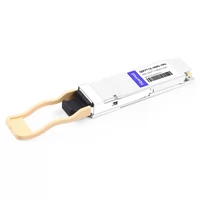
The short version up front, in case you’re mid-decision: QSFP112 backward compatibility works in the direction of the newer port, not the newer module.
Can a QSFP112 transceiver work in an older QSFP28 switch? Can existing 100G QSFP28 or 200G QSFP56 modules be reused in newer QSFP112 ports?
These questions often arise when network operators upgrade from 100G or 200G to 400G Ethernet. Although QSFP112, QSFP56, and QSFP28 share a similar physical form factor, mechanical compatibility does not guarantee electrical or operational compatibility.
The key distinction is between host-port backward compatibility and transceiver backward compatibility.
Many QSFP112 host ports can support older QSFP28 and QSFP56 modules, provided the platform supports the required electrical signaling, speed, and firmware configuration. However, standard 400G QSFP112 transceivers cannot operate at 400G in legacy QSFP28 or QSFP56 ports.
This guide explains the compatibility requirements, the differences between 25G NRZ, 50G PAM4, and 100G PAM4 signaling, and how to plan a phased migration from 100G to 400G while minimizing unnecessary infrastructure changes.
For a broader technical overview, see our complete QSFP112 400G guide.
Quick Answer: Is QSFP112 Backward Compatible?
Yes, but compatibility depends on the direction and capabilities of the host platform.
A QSFP112 port may support QSFP28 (100G) and QSFP56 (200G) transceivers when the host provides compatible multi-rate SerDes, firmware, and module management.
For example, NVIDIA ConnectX-7 adapters and BlueField-3 DPUs with QSFP112 interfaces support backward compatibility with selected QSFP56 and QSFP28 devices.
The reverse is different. A standard 400G QSFP112 transceiver requires a 100G-per-lane PAM4-capable host interface. An older QSFP28 port with 25G NRZ electrical lanes cannot provide the signaling required for native 400G QSFP112 operation.
Some specially designed modules or cable assemblies may support additional lower-speed operating modes, but such capabilities must be explicitly documented and validated.
The practical rule: A newer QSFP112 host port may support older-generation modules, but an older host port cannot automatically support a newer 400G QSFP112 transceiver.
Physical Fit Is Not Enough
QSFP28, QSFP56, and QSFP112 belong to the same four-lane QSFP form-factor family. Their similar mechanical interfaces make it possible to insert older-generation QSFP modules into compatible newer-generation cages.
However, three separate compatibility conditions must be considered:
- Mechanical compatibility: The module must fit the host connector and cage.
- Electrical compatibility: The host and module must support matching SerDes speeds and modulation formats.
- Operational compatibility: Firmware, module management, Ethernet operating modes, and FEC settings must be supported.
The most important differences lie in the electrical interface.
| Interface | Electrical Lanes | Signaling | Typical Aggregate Ethernet Rate |
| QSFP28 | 4 × 25G | NRZ | 100G |
| QSFP56 | 4 × 50G | PAM4 | 200G |
| QSFP112 | 4 × 100G | PAM4 | 400G |
For standard 400GbE operation, QSFP112 typically uses four electrical lanes operating at 106.25 Gb/s per lane, with a PAM4 symbol rate of 53.125 GBd.
NRZ signaling uses two amplitude levels to encode one bit per symbol. PAM4 uses four amplitude levels to encode two bits per symbol, allowing higher data rates without doubling the symbol rate.
However, PAM4 also introduces more demanding signal-integrity and error-correction requirements.
Therefore, a QSFP112 module cannot establish a native 400G link simply because it fits into an older QSFP28 cage.
Module detection is another important distinction.
A host may identify an inserted module through its management interface even when its electrical interface cannot establish a working link. Older devices may also have difficulty interpreting newer module management information.
Successful module detection does not confirm link compatibility.
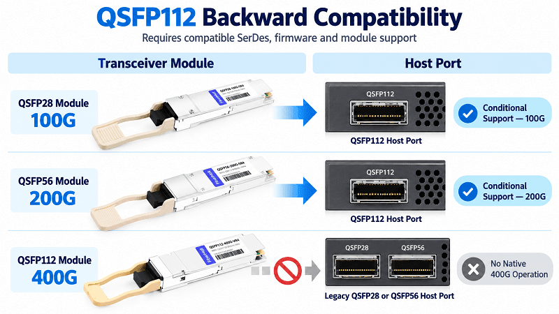
The Direction Rule: Who Accepts Whom
Three rows cover every real case.
| Direction | Result | Why |
| QSFP28 / QSFP56 module into a QSFP112 port | Works (100G / 200G) | Rate negotiation, if the ASIC has multi-rate SerDes |
| QSFP112 module into a QSFP28 / QSFP56 port | Detected, no link | Legacy port lacks 112G-PAM4 SerDes |
| QSFP112 module into a QSFP-DD port | 4-lane mode only | Uses 4 of 8 lanes; host must support 4 x 100G PAM4 |
That second row is the one people search for at 2 a.m. It’s also the one where a generic “backward compatible” claim gets a team into trouble, because some vendor pages list QSFP112 as compatible with QSFP28 equipment without saying which way the traffic flows.
There’s a quieter consequence too. Put a QSFP28 module into a QSFP112 port and that port is now a 100G port. Useful for coexistence, dangerous for capacity planning. If your oversubscription math assumed 400G per port, you just cut it by three quarters. The QSFP112 module types page details which variants you’d actually stock for each role.
Ready to compare the two ranges side by side? Explore our 400G QSFP112 transceivers and the 100G QSFP28 line before you lock a platform.
The ASIC Requirement Behind the Answer
The primary limitation in QSFP112 compatibility is the host electrical interface.
A 400G QSFP112 transceiver typically uses four 100G-class PAM4 electrical lanes. Supporting these lanes requires suitable SerDes hardware, signal integrity, and host-side PHY capabilities.
112G PAM4 Is Not a Firmware Update
Firmware cannot turn a 25G NRZ-only SerDes into a 100G-class PAM4 SerDes.
The required signaling capability must already exist in the host silicon and supporting electrical design.
Modern networking ASIC families may provide 100G-per-lane SerDes capabilities, but ASIC capability alone does not guarantee QSFP112 compatibility.
A complete host platform must also provide:
- A compatible QSFP112 physical interface
- Appropriate electrical lane mapping
- Supported Ethernet port speeds and operating modes
- Suitable module management and firmware
- Adequate power delivery and thermal management
The exact switch, router, NIC, or DPU model must therefore be checked rather than relying only on the ASIC family.
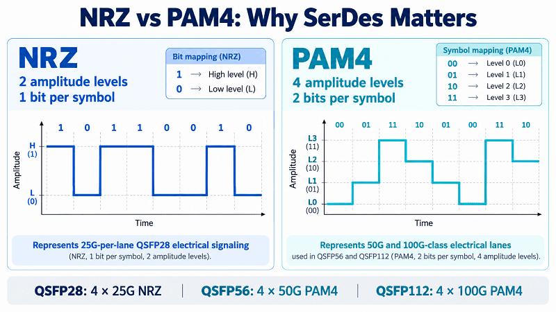
Multi-Rate Is What Makes the Forward Direction Work
Rate negotiation, where a QSFP28 or QSFP56 module runs in a QSFP112 port at its native speed, needs a multi-rate SerDes plus NOS support. NVIDIA documents it directly: QSFP112 cages in ConnectX-7 adapters and BlueField-3 DPUs are backward compatible and support QSFP56 200G with four lanes.
This is what makes QSFP112 forward compatible in one narrow sense and backward compatible in the practical one: the newer port reaches down to the older module, never the other way around.
Ravi ran into that exact split last quarter. He was refreshing an AI rack and assumed a full swap was needed. Instead he kept the existing QSFP56 200G optics in the new QSFP112 cages for the links that didn’t need 400G yet, and only bought 400G modules for the spine. He cut the first-order spend by roughly a third and staged the rest across two budget cycles.
For the wider NVIDIA picture, including part numbers, the QSFP112 in NVIDIA AI clusters page has it.
The Phased Upgrade Playbook: 100G QSFP28 to 400G QSFP112
Most guides hand you a pre-flight checklist. What’s missing is the sequence, which is what actually decides whether a migration lands on time.
Step 1: Decide Brownfield or Greenfield First
If you’re sitting on a large installed base of QSFP28 service, a QSFP-DD port accepts QSFP28 and QSFP56 modules natively and makes phased replacement easier. QSFP112 leans the other way, toward new builds where power and density matter. Our QSFP-DD vs QSFP112 decision guide works through that trade-off.
Step 2: Upgrade the Spine First
The classic phased path is a 400G spine with a 100G leaf. You migrate leaf ports on demand as bandwidth demands, reusing the legacy optics and fiber wherever the plant allows. It spreads capex and keeps the fabric live while you work.
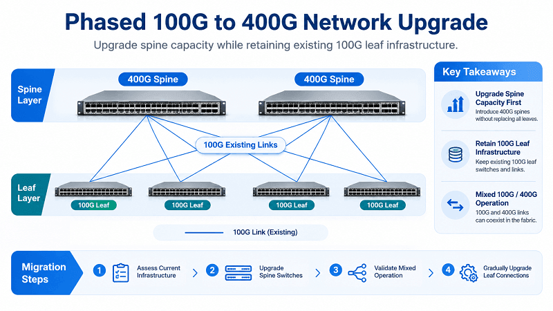
Step 3: Use Breakout to Coexist
A 400G DR4 port can break out to 4 x 100G, which lets 100G and 400G endpoints share a 400G spine port during the transition. It’s also the cleanest proof that a 400G port is backward compatible with 100G at the port level, not just at the module level. That single trick buys you time to re-cable without a hard cutover. The QSFP112 breakout guide covers the lane mapping and the cable types you’ll need.
Step 4: Verify Firmware, CMIS, and FEC
Each platform has a minimum NOS for QSFP112, and the CMIS version decides how much you can monitor. FEC has to match on both ends or links flap. The platform-by-platform floors, the CMIS 4.0 / 5.0 / 5.2 ladder, and the FEC rules are all in the QSFP112 compatibility guide, so we won’t re-list them here.
The Fiber-Plant Decision: What You Actually Replace
The installed fiber infrastructure can significantly influence the total cost and complexity of a 100G-to-400G migration.
Connector type, fiber category, optical reach, and available fiber count should be evaluated before selecting new transceivers.
Multimode SR4 Is Largely Reusable
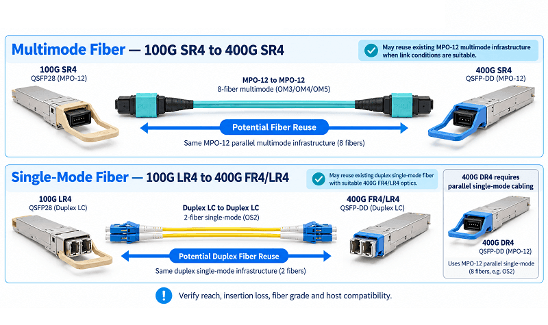
100GBASE-SR4 and 400GBASE-SR4 both use parallel multimode fiber architectures with four transmit and four receive optical paths.
As a result, existing MPO-12 multimode cabling may be reusable when upgrading from 100G SR4 to 400G SR4.
However, successful reuse depends on the installed fiber grade, link distance, connector polarity, insertion loss, and optical channel performance.
For example, standard 400GBASE-SR4 supports shorter distances than some 100GBASE-SR4 implementations.
400GBASE-VR4 provides another short-reach option, but its maximum reach is more limited.
Before reusing existing cabling, measure the channel loss and confirm that the installation satisfies the requirements of the selected 400G optical interface.
The same connector does not automatically guarantee the same supported distance or link budget.
Duplex Single-Mode Requires Careful Optical Selection
Many 100GBASE-LR4 deployments use duplex single-mode fiber with LC connectors.
By comparison, 400GBASE-DR4 uses parallel single-mode fiber and typically requires an MPO-12 interface.
A direct migration from duplex 100G LR4 to parallel 400G DR4 therefore requires a different optical cabling arrangement.
However, replacing the existing duplex fiber is not always necessary.
A 400GBASE-FR4 interface supports duplex single-mode connections with a nominal reach of 2 km, while 400GBASE-LR4 supports longer duplex single-mode links.
These optical interfaces may allow operators to preserve existing fiber pairs, provided the optical budget, link distance, connector condition, and host compatibility requirements are satisfied.
In many cases, selecting an appropriate duplex 400G optical interface is more practical than rebuilding the fiber plant for parallel optics.
Match the Variant to the Plant
Different 400G optical interfaces serve different cabling environments.
| 400G Optical Interface | Fiber Type | Typical Connector | Standard Reach |
| 400GBASE-VR4 | Multimode | MPO-12 | 30m OM3 / 50m OM4 |
| 400GBASE-SR4 | Multimode | MPO-12 | 60m OM3 / 100m OM4 |
| 400GBASE-DR4 | Single-mode | MPO-12 | 500m |
| 400GBASE-FR4 | Single-mode | Duplex LC | 2km |
| 400GBASE-LR4 | Single-mode | Duplex LC | 10km |
The values above represent standard interface reaches. Actual product availability and compatibility must be verified for the selected form factor and host equipment.
What This Means for Cost and Power
The Migration Economics
The upgrade cost is dominated by the fiber plant, not the optics. A multimode SR4 refresh is optics-only. A duplex single-mode rebuild means re-cabling, and that’s where the project scope balloons. Price the two scenarios before you commit, and the QSFP112 price guide gives you the per-port figures to build the model.
Power and the Cage
A QSFP112 module sits in CMIS Power Class 6, up to 12W. A QSFP28 leg is Class 5, up to 5W. A cage that can’t source the class won’t initialize the module, which is a hardware limit rather than a config error. For the rack-level view, the QSFP28 thermal planning guide covers the method, and it applies to a mixed QSFP112 / QSFP28 rack just as well.
The 800G Dead-End: Planning Beyond 400G
Standard QSFP112 interfaces provide four 100G-class electrical lanes for 400G connectivity.
They are not designed to provide native 800G or 1.6T operation through the same standard four-lane 100G electrical interface.
As network requirements grow beyond 400G, operators may need platforms with higher-speed electrical interfaces and different transceiver architectures.
QSFP-DD800 and modern OSFP implementations provide options for 800G networking, while newer optical architectures support further increases in capacity.
However, future upgrade capability depends on the host ASIC, electrical interface, physical port design, power budget, and platform support.
A transceiver replacement alone cannot increase a port beyond its underlying hardware capabilities.
For organizations expecting substantial bandwidth growth, the platform’s long-term roadmap should be evaluated before committing to a particular form factor.
QSFP28 to QSFP112 Migration Checklist
Run these in order before you order hardware.
1. Confirm the target switch or NIC has a 112G-PAM4-class ASIC, not just a QSFP cage.
2. Confirm the NOS is at or above the vendor’s QSFP112 floor.
3. Classify the fiber plant: multimode SR4 (reusable), duplex single-mode LR4 (rebuild), or parallel single-mode DR4 (new).
4. Pick the variant that matches the plant.
5. Confirm CMIS 5.2 for production monitoring and matching RS(544,514) KP4 FEC.
6. Size the power budget for Class 6 optics in mixed cages.
7. Phase the rollout: spine first, leaf on demand, breakout to coexist.
8. Test that any legacy optics you plan to keep negotiate down as expected.
Step eight is the one that surprises people. Rate negotiation is a claim until you verify it on your own firmware build.
FAQ
Is QSFP112 backward compatible with QSFP28?
Yes, many QSFP112 host ports support QSFP28 modules when the platform provides compatible 100G electrical signaling, firmware, and transceiver management.
However, a standard 400G QSFP112 transceiver cannot operate at 400G in a legacy QSFP28 port.
Can I use a QSFP28 module in a QSFP112 port?
Usually, on host platforms that explicitly support QSFP28 backward compatibility.
The QSFP28 module typically operates at its supported 100G rate rather than the QSFP112 port’s maximum 400G capability.
Can I plug a QSFP112 module into a QSFP28 port?
The module may fit mechanically, but a standard 400G QSFP112 transceiver cannot establish a native 400G link through a QSFP28-only electrical interface.
Any lower-speed operation requires explicit support from both the module and the host.
Is QSFP112 backward compatible with QSFP56?
Many QSFP112 host ports support QSFP56 200G modules through compatible multi-rate SerDes and firmware.
A standard 400G QSFP112 transceiver does not automatically support operation in a legacy QSFP56 port.
Does QSFP112 work in a QSFP-DD port?
It may work in a compatible QSFP-DD host that supports the required four-lane electrical operating mode.
Mechanical insertion alone does not guarantee 400G link operation.
Can I reuse my QSFP28 fiber for QSFP112?
Yes, in some deployments.
Existing MPO-12 multimode cabling may support migration from 100G SR4 to 400G SR4 if the fiber grade, distance, and optical budget meet the new requirements.
Duplex single-mode installations may also be reusable with suitable 400G FR4 or LR4 optics.
Does QSFP112 require CMIS 5.2?
Not universally.
The required CMIS support depends on the specific transceiver and host platform. Always verify the manufacturer’s documented management-interface requirements.
Should I migrate to QSFP112 or QSFP-DD?
QSFP112 can be appropriate for four-lane 400G deployments, particularly when the host platform and transceiver ecosystem match the intended network architecture.
QSFP-DD may offer greater flexibility in deployments that require eight-lane interfaces, certain legacy QSFP module combinations, or an 800G platform roadmap.
The final decision should consider platform compatibility, power, density, available optics, cabling, and future capacity requirements.
Where This Leaves You
QSFP112 backward compatibility is primarily determined by the capabilities of the host port rather than the physical similarity of the transceiver.
Many newer QSFP112 ports can operate with older QSFP28 and QSFP56 modules when the required electrical signaling and firmware support are available.
However, standard 400G QSFP112 transceivers cannot deliver native 400G operation through legacy 100G or 200G host interfaces.
For a successful migration, the critical steps are to verify host compatibility, select the appropriate optical interface, evaluate the existing fiber infrastructure, and validate the complete link configuration.
Reusing compatible optics and cabling can reduce upgrade costs, but it should never come at the expense of signal integrity or link reliability.
If you are planning a QSFP28 to QSFP112 migration, explore FiberMall’s 400G QSFP112 transceivers and QSFP112 module options.
FiberMall can help evaluate transceiver compatibility, optical reach, and cabling requirements for 100G, 200G, and 400G network upgrades.
Related Products:
-
 QSFP112-400G-SR4 400G QSFP112 SR4 PAM4 850nm 100m MTP/MPO-12 OM3 FEC Optical Transceiver Module
$400.00
QSFP112-400G-SR4 400G QSFP112 SR4 PAM4 850nm 100m MTP/MPO-12 OM3 FEC Optical Transceiver Module
$400.00
-
QSFP112-400G-DR4 400G QSFP112 DR4 PAM4 1310nm 500m MTP/MPO-12 with KP4 FEC Optical Transceiver Module
$500.00
-
QSFP112-400G-FR1 4x100G QSFP112 FR1 PAM4 1310nm 2km MTP/MPO-12 SMF FEC Optical Transceiver Module
$800.00
-
QSFP112-400G-FR4 400G QSFP112 FR4 PAM4 CWDM 2km Duplex LC SMF FEC Optical Transceiver Module
$600.00
-
QSFP112-400G-LR4 400G QSFP112 LR4 PAM4 CWDM 10km Duplex LC SMF FEC Optical Transceiver Module
$1000.00
-
FiberMall QSFP112-400G-VR4 Compatible 400G QSFP112 VR4 PAM4 850nm 50m MTP/MPO-12 OM4 FEC Optical Transceiver Module
$385.00