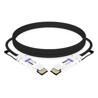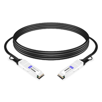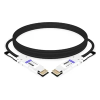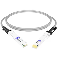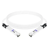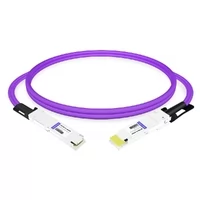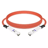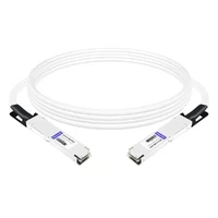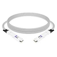

A DAC cable is usually the better choice for short, fixed data center links under about 3 m, where cost, power consumption, and latency are important considerations. An optical module paired with fiber is generally the better choice when a link needs to reach farther, connect through patch panels, support optical diagnostics, or accommodate future network upgrades.
Both solutions can use compatible switch port form factors, but that is where the similarity largely ends. Two links can share a QSFP-DD port and a 400G data rate, yet one uses a single copper cable assembly while the other requires two optical transceivers and a separate fiber cable.
The DAC cable vs optical module decision is not simply about comparing specifications. It is about how the link will be installed, monitored, maintained, and upgraded.
DAC vs Optical Module at a Glance
The short answer: a direct attach copper cable (DAC) is a fixed-length copper assembly with transceiver-style connectors at both ends, while an optical module is a pluggable transceiver that converts electrical signals into optical signals and requires a separate fiber cable.
| Factor | DAC Cable | Optical Module + Fiber |
| Medium | Shielded twinax copper | Optical transceivers with MMF or SMF |
| Signal path | Electrical end-to-end | Electrical → Optical → Electrical |
| Typical reach | 7–10 m at 10G; 1–5 m at 100G; typically up to 2 m at 400G/800G passive DAC. AEC can extend copper reach. | SR: 70–100 m; DR: 500 m; FR: 2 km; LR: 10 km, depending on the specific PMD |
| Power per end | Negligible for passive DAC; active copper power varies by design | Approximately 3.5–4 W at 100G; 8–14 W at 400G; 14–18 W at 800G; some 800G LPO designs at 8 W or less; 20–30 W for some coherent ZR modules |
| Cost basis | One cable assembly | Two modules plus fiber and connectors |
| Diagnostics | Cable identification and link/error information; no optical Tx/Rx power monitoring | DOM/DDM on supported modules for Tx power, Rx power, temperature, and laser bias |
| Serviceability | Replace the complete assembly | Replace one module or the fiber cable independently |
| Best use | Fixed, short-reach in-rack connections | Longer links, structured cabling, and scale-out networks |
These figures are representative examples rather than universal specifications. Actual reach and power consumption depend on the data rate, PMD, cable design, fiber grade, form factor, and vendor.
Short version: choose DAC for short, fixed in-rack links; choose optical modules when reach, diagnostics, and cabling flexibility matter more.
Explore FiberMall’s DAC, AOC, ACC, and AEC cables and 200G, 400G, and 800G optical transceivers to compare lengths, speeds, and coding options.
What Each Option Actually Is
DAC Cable: One Assembly, Two Fixed Ends
A DAC is a shielded twinaxial copper cable with transceiver-style connectors permanently attached to both ends. The connectors fit compatible SFP, SFP28, QSFP, QSFP-DD, and OSFP cages, allowing the switch to recognize the assembly as a pluggable cable connection.
The signal remains electrical throughout the connection. A passive DAC does not require optical transmitters, photodetectors, or optical conversion circuitry, which helps reduce its cost and power consumption compared with optical transceivers.
The cable assembly typically contains EEPROM information identifying the vendor, cable length, and cable type. This is why vendor coding and platform compatibility matter.
Passive DAC relies on the host SerDes for signal transmission. Active copper cables use signal-conditioning electronics, such as redrivers or retimers, to extend reach beyond passive copper limits.
FiberMall’s guide to what a DAC cable is covers the passive, ACC, and AEC variants.
Optical Module: One Component of a Link
An optical transceiver module is a pluggable device that converts electrical signals into modulated optical signals for transmission and converts received optical signals back into electrical signals.
It contains a transmitter, receiver, control circuitry, and, depending on the design, digital diagnostic monitoring capabilities.
The module is only one part of the complete link. A separate fiber cable is required, and the fiber type, connector, end-face polish, wavelength, and link budget all become part of the design.
For example, a 400G SR8 implementation commonly uses an MPO-16 connector, while a 100G SR4 implementation typically uses an MPO-12 connector. Exact connector types and polish requirements must be verified against the transceiver datasheet.
FiberMall’s optical transceiver, AOC, DAC, and ACC overview explains the pluggable model.
The Five Differences That Decide the Link
Reach gets most of the attention, but four other factors determine whether a link is economical to install and maintain over its lifetime.
Distance and Speed: Where Copper Stops
The DAC vs optical module distance gap widens as lane rates increase. At 10G, passive copper links of 7–10 m are commonly available. At higher data rates, insertion loss and crosstalk become increasingly difficult to manage, making passive copper assemblies shorter.
At 400G and 800G, passive DAC connections are generally limited to approximately 2 m, while AEC solutions can extend copper connectivity farther, depending on the cable and platform.
The following table provides representative reach examples.
| Speed | Common Form Factors | Passive DAC Reach (Typical) | Optical Module Reach Examples |
| 10G | SFP+ | 7–10 m | SR: 300 m OM3 / 400 m OM4; LR: 10 km |
| 25G | SFP28 | 3–5 m | SR: 70 m OM3 / 100 m OM4; LR: 10 km |
| 40G | QSFP+ | 5–7 m | SR4: 100 m OM3 / 150 m OM4; LR4: 10 km |
| 100G | QSFP28 | 3–5 m | SR4: 70 m OM3 / 100 m OM4; DR1: 500 m; FR1/CWDM4: 2 km; LR4: 10 km |
| 200G | QSFP56 | 2–3 m | SR4: 70 m OM3 / 100 m OM4; DR4: 500 m; FR4: 2 km |
| 400G | QSFP-DD, OSFP | Up to approximately 2 m | SR8: 70 m OM3 / 100 m OM4; DR4: 500 m; FR4: 2 km; LR4: 10 km |
| 800G | OSFP, QSFP-DD | Up to approximately 2 m for CR8 | SR8: 60 m OM3 / 100 m OM4; DR8: 500 m; 2×FR4: 2 km; 2×LR4: 10 km |
| 1.6T | OSFP-family, depending on platform | Vendor-specific; no universal passive DAC reach | Emerging 1.6T PMD options; verify the specific standard and product datasheet |
The optical distances above are standards-based examples. OM3 and OM4 distances are different, even for the same optical interface. Single-mode reach also depends on the exact PMD rather than the data rate alone.
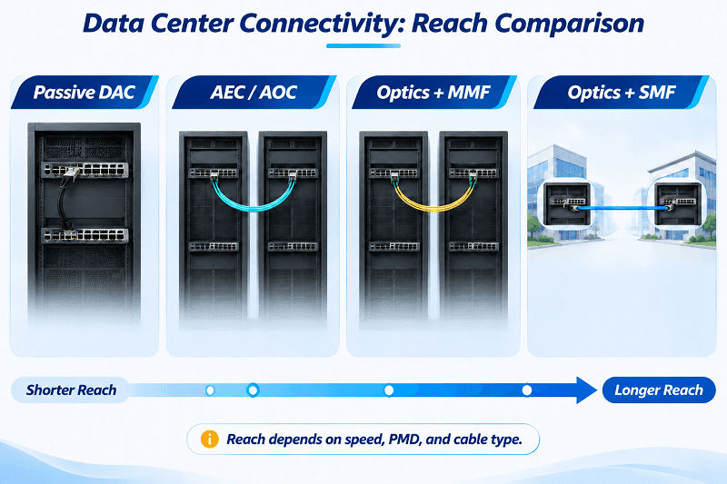
For DAC cables, the listed distances are typical product ranges, not guaranteed limits. Wire gauge (AWG), host SerDes capability, connector quality, channel insertion loss, and cable construction all affect the achievable reach.
IEEE 802.3ck defines important high-speed electrical interfaces, while IEEE P802.3dj covers next-generation Ethernet technologies, including 1.6T. Check the latest standard status and individual vendor specifications before making 1.6T reach claims. The OIF CEI specifications also provide important context for the development of high-speed electrical interfaces.
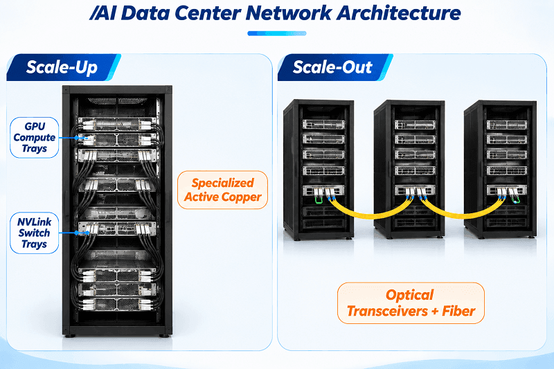
The 2026 framing: copper remains important for short-reach scale-up connectivity, while optical links are widely used for longer-reach scale-out connectivity between racks and rows. HPCwire’s analysis of where copper ends and optical begins makes the same point.
Power Consumption and Cooling at 400G and 800G
A passive DAC consumes very little power, generally limited to the small amount required by its cable identification electronics. The power consumed by the host switch port itself is separate from the cable’s power consumption.
Active copper cables, including AEC and ACC, require additional power for signal conditioning. Their actual consumption depends on the data rate and internal electronics.
Optical modules require more power because they contain optical and electronic components. Typical examples include approximately 3.5–4 W for some 100G modules, 8–14 W for many 400G modules, and 14–18 W for some 800G modules. Some 800G LPO implementations can operate at 8 W or less, while coherent ZR modules may consume 20–30 W, depending on the generation and model.
These are representative product values, not fixed industry limits.
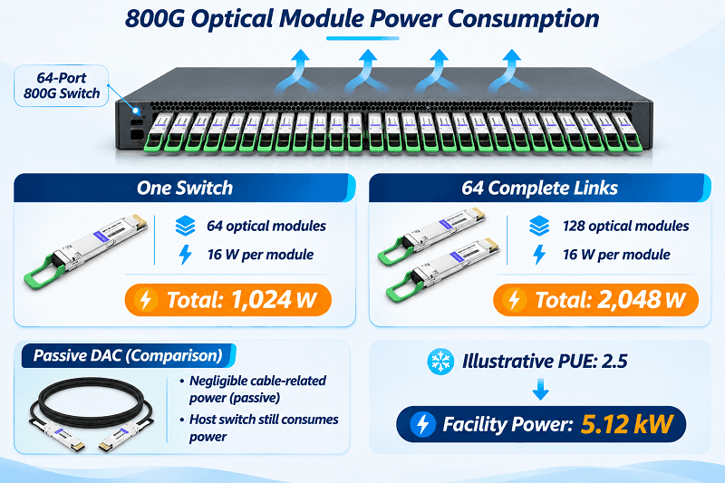
Do the math at the switch level. A fully populated 64-port 800G switch has 64 optical module ends. At 16 W per module, the optical modules on that switch consume approximately 1,024 W.
If all 64 ports connect to another device with a corresponding optical module at the remote end, the 64 complete links contain 128 module ends:
128 × 16 W = 2,048 W.
For an illustrative facility PUE of 2.5, the corresponding facility power attributable to these optical modules is approximately 5.12 kW.
At $0.12 per kWh, continuous operation would cost approximately $5,380 per year for the complete set of 64 links. This calculation covers both ends of the links, not just one switch.
A PUE of 2.5 is a scenario assumption rather than a typical industry average. For an actual deployment, use the data center’s measured PUE and electricity rate.
The same 64 links using passive DAC would have substantially lower cable-related power consumption, although the host switch ports still consume power.
Cost per Link, Not per Part
The DAC cable vs optical module cost comparison only makes sense when calculated per complete link, including everything required to establish the connection.
| Cost Element | DAC Link | Optical Link |
| Transceivers | Integrated into the cable assembly | Two separate modules |
| Cable | Integrated into the assembly | Fiber trunk or patch cord |
| Patch panels | Not designed for conventional fiber patch-panel connections | Compatible with structured fiber cabling |
| Spares | Complete assemblies in different lengths | Modules and fiber cables tracked separately |
| Relative hardware cost | 1× | Can be several times higher, depending on speed and product |
A 2 m 400G DAC commonly lists between $70 and $150. A pair of third-party 400G optical modules may cost between $300 and $700 before fiber is included. These are illustrative street-price ranges, not fixed market prices or a FiberMall quotation.
Optical links can recover part of their initial premium through infrastructure reuse. A properly designed fiber plant can support multiple generations of network equipment, while a copper assembly is generally tied to a particular speed, length, and interface.
Actual reuse depends on fiber grade, fiber count, polarity, connector type, end-face polish, and the optical link budget. Connector transitions such as MPO-12 to MPO-16 or UPC to APC may require dedicated conversion assemblies rather than direct connections.
Latency and Signal Integrity
A passive DAC cable introduces approximately 5 ns of propagation delay per meter, similar to fiber-optic cabling. The cable itself does not introduce optical conversion or optical-module DSP processing.
However, total link latency depends on the electrical interface, host SerDes, retimers, and FEC requirements. Some high-speed copper links also require FEC, which can introduce additional processing latency.
Optical module latency varies considerably by transceiver architecture. DSP processing may contribute tens to around 100 ns, while FEC latency depends on whether error correction is implemented in the host or inside the module.
For example, one published 400G FR4 latency analysis estimates approximately 100 ns for module DSP processing and another 100 ns for host-side KP4 FEC. This is an example rather than a universal latency specification.
The important distinction is that the complete electrical or optical channel must be evaluated, not just the cable.
Copper has its own signal-integrity limits. At high lane rates, insertion loss, crosstalk, and connector reflections reduce the available signal margin. This is why an 800G DAC that passes a laboratory test can still experience intermittent link issues in a hot rack with poor cable routing or an excessively tight bend radius.
Diagnostics, Serviceability, and Fiber Reuse
Passive DAC provides cable identification and basic link information, but it generally does not provide optical Tx/Rx power measurements. When a link flaps at 2 a.m., the switch may not be able to determine whether the issue comes from the cable, the port, or the far-end device.
Optical transceivers supporting DOM/DDM can report parameters such as Tx power, Rx power, temperature, and laser bias current. These measurements provide additional information for troubleshooting.
Serviceability follows the same pattern. A failed DAC requires replacement of the complete cable assembly, which may mean removing a cable from a populated rack.
With an optical link, a failed module can be replaced independently while leaving the fiber cabling in place. A damaged fiber patch cord can also be replaced without changing the transceivers.
Fiber reuse is another long-term advantage. A structured fiber plant can support 100G, 400G, and 800G upgrades by changing transceivers, provided the installed fiber grade, fiber count, polarity, connector interfaces, and insertion-loss budget remain compatible.
Some upgrades may still require conversion harnesses, fanout cables, or new fiber trunks.
Fixed Assembly vs Structured Cabling
A conventional DAC assembly is not designed to terminate into a passive fiber-optic patch panel. Its fixed transceiver-style connectors and copper construction make it unsuitable for many structured fiber-cabling designs.
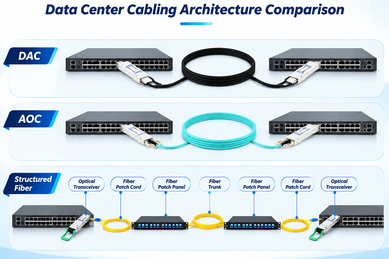
Structured cabling separates active electronics from the passive fiber plant. Optical modules plug into switches, while fiber trunks and patch cords connect equipment through patch panels. Technicians can reconfigure connections without replacing the entire active cable assembly.
A DAC combines both ends and the transmission medium into one component. This is efficient for a fixed rack but less flexible in an environment where cabling changes frequently.
AOC occupies the middle ground. It is a fixed cable assembly with optical components and fiber integrated into the cable, commonly available in lengths from a few meters to 100 m or more, depending on the product.
Like DAC, an AOC is not normally designed for independent termination and patching through a conventional passive fiber panel. A cable failure generally requires replacement of the complete assembly.
For a fuller comparison, see DAC vs AOC cable.
When to Use DAC vs Optical Module
Choose a DAC cable if:
- Both ends sit in the same rack, and the run is under about 3 m at 100G or higher.
- Power consumption and cooling are important considerations.
- The link is part of a fixed AI scale-up topology where short copper connections are supported.
- The switch ports support the specific DAC form factor, speed, and cable coding.
Choose an optical module if:
- The link crosses racks, rows, halls, or buildings.
- The design uses patch panels, structured cabling, or pre-terminated fiber trunks.
- You need DOM diagnostics or independent replacement of modules and fiber cables.
- The link requires WDM, longer reach, or an existing fiber infrastructure.
- Future network upgrades require greater cabling flexibility.
| Distance Band | Default Choice | Notes |
| 0–3 m | Passive DAC | Verify reach at the target speed, cable AWG, and platform |
| 3–7 m | AEC or AOC | AEC extends copper reach; AOC provides a fixed optical connection |
| 7–100 m | AOC or optics + MMF | Structured cabling generally favors pluggable optics |
| 100 m–10 km | Optics + SMF | Select DR, FR, or LR based on the required reach |
| Beyond 10 km | LR, ER, or coherent optics | Confirm the complete optical link budget and FEC requirements |
AI Scale-Up vs Scale-Out
AI rack architectures have changed the way data center connectivity is designed.
A GB200 NVL72 rack uses four NVLink cable cartridges containing more than 5,000 active copper cables. These specialized connections form part of NVIDIA’s rack-scale NVLink interconnect architecture, connecting compute trays and NVLink switch trays across the 72-GPU NVLink domain.
These are not simply conventional QSFP-DD or OSFP DAC assemblies. They are specialized copper interconnects designed for NVIDIA’s rack-scale architecture.
Inside the rack, short-reach copper connectivity provides high bandwidth and low latency while avoiding the power consumption of optical transceivers.
Between racks, optical transceivers and fiber are widely used for scale-out connectivity. AOC and active copper solutions may also be suitable for shorter rack-to-rack connections, depending on distance, topology, and platform compatibility.
Use NVIDIA’s LinkX documentation to confirm compatibility with supported connectivity solutions.
A 48-Port TCO Example
Consider 48 × 100G links in one rack, each with a 2 m reach and a three-year operating life.
| Item | All Passive DAC | All 100G SR4 Optics |
| Link hardware | 48 assemblies at about $35–60 each | 96 modules at about $50–80 each, plus 48 MPO patch cords |
| Hardware subtotal | About $1,700–2,900 | About $5,800–9,100, including assumed fiber patch-cord costs |
| Power at the cable/module ends | Negligible cable power | About 336 W |
| Facility power at PUE 2.5 | Very low cable-related load | About 840 W |
| Three-year energy consumption | Negligible at the cable level | About 22,000 kWh, approximately $2,650 at $0.12/kWh |
The optical hardware estimate includes an assumed budget for 48 MPO patch cords. Actual costs depend on cable length, fiber grade, connector configuration, and supplier pricing.
The power calculation for optical links assumes 96 modules operating continuously at 3.5 W each:
96 × 3.5 W = 336 W.
Applying an illustrative PUE of 2.5 gives approximately 840 W of facility power. Over three years of continuous operation, this equals approximately 22,000 kWh, or $2,650 at $0.12 per kWh.
At 2 m, passive DAC generally wins on hardware cost and cable power consumption. Optical links become more attractive when the rack requires frequent reconfiguration, an existing fiber infrastructure is available, optical diagnostics are important, or future upgrades require greater flexibility.
Prices and power assumptions are illustrative, not a FiberMall quotation. Replace them with actual product specifications and current pricing before making a purchasing decision.
See FiberMall’s QSFP-DD price and TCO guide for 400G and 800G economics.
Compatibility, Coding, and Troubleshooting
Both DAC assemblies and optical modules can contain EEPROM-based identification information and may trigger an “unsupported transceiver” error if the platform does not recognize them.
A DAC is coded for a particular vendor, speed, length, and cable type. Some switches accept a broad range of MSA-compliant assemblies, while others enforce vendor-specific compatibility checks.
Optical modules add further compatibility requirements, including wavelength, fiber type, reach class, connector interface, lane mapping, and host FEC requirements.
The same form factor does not guarantee interchangeability. Before ordering, check lane rate, PAM4 support, breakout lane mapping, FEC compatibility, firmware, and vendor coding.
For example, a 400G port configured to break out into 4 × 100G requires a compatible transceiver or cable assembly and the correct lane mapping and fiber polarity.
Common troubleshooting symptoms include:
- Link flap or CRC errors: Possible causes include marginal insertion loss, excessive cable bending, poor connector contact, or a copper assembly operating near its reach limit.
- No link: Check speed configuration, vendor coding, interface compatibility, and breakout lane mapping.
- Intermittent optical faults: Check dirty endfaces, damaged connector polish, incorrect fiber polarity, and mis-keyed MPO connectors.
DAC Cable vs Optical Module FAQ
What is the difference between a DAC cable and an optical module?
A DAC is a fixed copper assembly with transceiver-style connectors at both ends. An optical module is a pluggable transceiver that converts electrical signals into optical signals and requires a separate fiber cable.
Can I plug a DAC cable into an SFP or QSFP port instead of a transceiver?
Yes, provided the port supports the DAC’s form factor, speed, cable type, and coding. The switch recognizes the DAC as a pluggable cable assembly, although some platforms enforce vendor-specific compatibility checks.
Is a DAC cable better than an optical module?
A DAC is generally better for short, fixed, power-sensitive connections, particularly in-rack links under 3 m. Optical modules are generally better for longer distances, structured cabling, optical diagnostics, and network reconfiguration.
Neither solution is universally better. The correct choice depends on the link requirements and supported hardware.
How far can a DAC cable reach compared with an optical module?
Passive DAC reach varies by data rate and cable construction. Representative ranges include 7–10 m at 10G, 3–5 m at 100G, and approximately 2 m at 400G and 800G.
Optical reach depends on the PMD and fiber type. Common examples include 70–100 m for SR, 500 m for DR, 2 km for FR, and 10 km for LR.
For multimode links, OM3 and OM4 can have different maximum distances. Always check the specific transceiver datasheet.
Are DAC cables cheaper than optical modules?
Yes, in most short-reach applications. A DAC is one complete cable assembly, while an optical link requires two transceivers plus fiber and connectors.
The price difference depends on data rate, product specifications, vendor, and whether fiber infrastructure is already available.
Do DAC cables support DOM or diagnostics?
Passive DAC cables generally do not provide optical Tx/Rx power measurements because they do not transmit optical signals.
Optical modules supporting DOM/DDM can report parameters such as Tx power, Rx power, temperature, and laser bias current. Active copper cables may provide additional cable-management information, depending on their design.
Can a DAC cable connect through a patch panel?
A conventional DAC assembly is not designed for independent termination and patching through a passive fiber-optic patch panel. For structured fiber cabling, use optical modules with compatible fiber trunks or patch cords.
Which is better for 400G or 800G links?
For short in-rack connections under approximately 2 m, passive DAC is often a cost-effective choice. AEC can extend copper reach when the platform supports it.
For longer distances, structured cabling, or connections between rows, optical modules or AOCs are generally more suitable.
Always verify the actual reach, power consumption, connector type, and platform compatibility before selecting a solution.
Related Products:
-
 QDD-200G-PC50CM 0.5m (1.6ft) 200G QSFP-DD to QSFP-DD Passive Direct Attach Copper Twinax Cable
$45.00
-
QSFP56-200G-PC50CM 0.5m (1.6ft) 200G QSFP56 to QSFP56 PAM4 Passive Direct Attach Copper Twinax Cable
$45.00
-
QSFPDD-400G-PC50CM 0.5m (1.6ft) 400G QSFP-DD to QSFP-DD PAM4 Passive Direct Attach Copper Twinax Cable
$70.00
-
QSFP-DD-400G-AC3M 3m (10ft) 400G QSFP-DD to QSFP-DD PAM4 Active Direct Attach Copper Twinax Cable
$350.00
-
QDD-OSFP-FLT-PC50CM 0.5m (1.6ft) 400G QSFP-DD to OSFP Flat Top PAM4 Passive Direct Attached Cable
$154.00
-
OSFP-FLT-400G-PC50CM 0.5m (1.6ft) 400G NDR OSFP to OSFP PAM4 Passive Direct Attached Cable, Flat top on one end and Flat top on other
$110.00
-
QDD-OSFP-FLT-AEC50CM 0.5m (1.6ft) 400G QSFP-DD to OSFP Flat Top PAM4 Active Electrical Copper Cable
$1200.00
-
OSFP-FLT-800G-AC3M 3m (10ft) 800G Twin-port 2x400G OSFP to 2x400G OSFP InfiniBand NDR Active Copper Cable, Flat top on one end and Flat top on the other
$600.00
-
OSFP-FLT-800G-PC2M 2m (7ft) 2x400G OSFP to 2x400G OSFP PAM4 InfiniBand NDR Passive Direct Attached Cable, Flat top on one end and Flat top on the other
$300.00
-
OSFP-800G-PC50CM 0.5m (1.6ft) 800G Twin-port 2x400G OSFP to 2x400G OSFP InfiniBand NDR Passive Direct Attach Copper Cable
$105.00