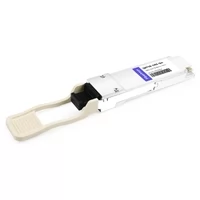
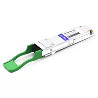
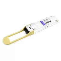
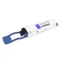
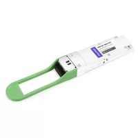
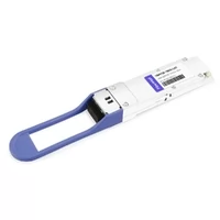
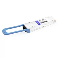
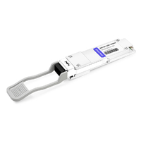
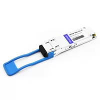
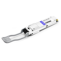
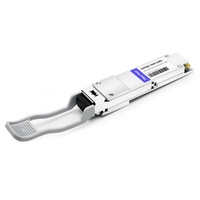
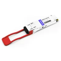
Marcus shipped twelve QSFP28 modules back to his supplier. All twelve tested good. The RMA process cost his team roughly $12,000. A $5 fiber cleaning pen fixed what two weeks of logistics couldn’t.
QSFP28 troubleshooting isn’t about memorizing commands. It’s about knowing where to look first. At 100G, the difference between a five-minute fix and a five-day RMA usually comes down to diagnostic discipline. Most engineers skip the physical layer and dive straight into CLI logs. That’s backwards.
This guide gives you a systematic 5-phase workflow that resolves roughly 90% of QSFP28 issues without guesswork. You’ll get vendor-specific diagnostic commands, a DOM interpretation framework, and the isolation logic that prevents unnecessary returns. If you need background on the technology first, start with our complete QSFP28 guide.
The 5-Phase QSFP28 Troubleshooting Workflow
Many QSFP28 troubleshooting cases are resolved in Phase 1. Skip it and you’ll waste days chasing ghosts.
Most engineers jump straight to logs, BER analysis, and firmware upgrades. That’s a mistake. The physical layer is where most failures live. A systematic approach to QSFP28 troubleshooting saves time, prevents unnecessary hardware returns, and gets your links stable faster.
| Phase | Focus | Approximate Resolution Rate |
| Phase 1 | Physical Verification | ~40% |
| Phase 2 | Module Recognition & EEPROM | ~25% |
| Phase 3 | Configuration Verification | ~15% |
| Phase 4 | Signal Quality, BER & Thermal | ~10% |
| Phase 5 | Isolation Testing | ~10% |
These percentages should be treated as field-experience estimates, not universal failure statistics. Your actual results will depend on platform, module type, cabling quality, firmware version, and deployment environment.
Each phase builds on the previous one. Don’t move to Phase 2 until you’ve confirmed physical integrity. Don’t dive into BER analysis in Phase 4 until you’ve verified the module is recognized and configured correctly. This structured approach to QSFP28 troubleshooting prevents the guesswork that wastes engineering hours.
Phase 1: Physical Verification
That “dead” module might just need 30 seconds and a lint-free wipe. In QSFP28 troubleshooting, the simplest fix is often the right one.
Sarah, a data center tech in Dallas, spent three hours on a classic QSFP28 troubleshooting case — a 100G SR4 link that wouldn’t establish. She checked configs, verified port status, and even swapped the switch port. Nothing worked. Then she pulled the module, inspected the MPO connector under a fiber microscope, and found a single hair trapped between two fibers. Thirty seconds of cleaning. Link came up immediately. The phantom bad optic was just dirty glass.
Visual Inspection Checklist
Start with your eyes and your hands. Most physical issues are obvious once you know what to look for:
- Module seating: Push firmly until the latch clicks. Partial insertion is a common cause of intermittent lane errors.
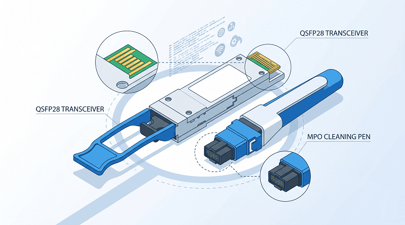
- Golden fingers: Check the electrical contacts for corrosion, debris, or bent pins. A single damaged contact can affect one or more 25G lanes.
- Connector damage: Look for cracked ferrules, pulled boots, damaged MPO guide pins, or kinked cables.
- Dust caps: Modules and patch cords stored without dust caps are already at high risk of contamination.
Proper cable hygiene is the foundation of effective QSFP28 troubleshooting. Connector contamination alone accounts for roughly 65-70% of all 100G link failures. For a deeper look at cable types and compatibility, see our QSFP28 cable guide.
Fiber Connector Cleaning Procedure
Connector contamination causes the majority of 100G link failures. In QSFP28 troubleshooting, the fiber end-face is always worth checking first.
1. Inspect first: Use a 200x or 400x fiber microscope. Look for dust, oil, or debris on the end-face. Never clean what you haven’t inspected.
2. Wet-to-dry method: Apply one drop of fiber cleaning fluid to a lint-free wipe. Draw the connector across the wet section, then across a dry section. For UPC connectors only — never use alcohol on APC.
3. Verify connector type: QSFP28 SR4 uses MPO-12 connectors. LR4 and CWDM4 use duplex LC. Make sure you’re cleaning the right interface.
4. Re-inspect: Clean until the end-face passes inspection. A single retry takes 30 seconds. A failed link costs hours.
Cable and Environmental Checks
Bend radius: Single-mode fiber needs a 30mm minimum bend radius. Tight cable management can induce micro-bending loss — an easy-to-miss variable in QSFP28 troubleshooting.
Strain relief: Heavy MPO trunk cables pulling on the module can cause intermittent contact.
Airflow and temperature: Modules in the top row of a dense chassis ingest pre-heated air. Upper ports can run 8-12°C hotter than lower ports.
Phase 2: Module Recognition & EEPROM
Your switch might be lying about whether it sees the module. QSFP28 not detected is one of the most common — and most frustrating — symptoms you’ll encounter.
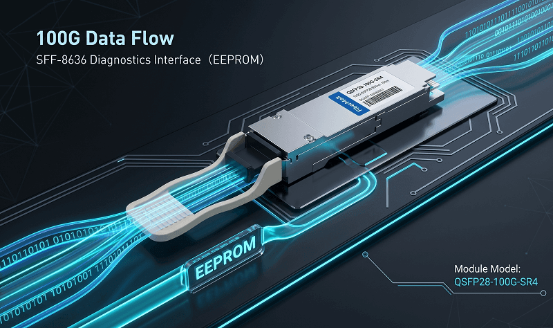
QSFP28 modules communicate with host switches via the SFF-8636 specification. This defines the EEPROM memory map that stores vendor ID, speed capabilities, and diagnostic parameters. Understanding SFF-8636 is essential for any serious QSFP28 troubleshooting workflow.
The module stores critical information in specific EEPROM bytes:
Byte 128: Identifier
Byte 130: Connector type
Bytes 131–138: Specification compliance codes
Bytes 148–163: Vendor name
Bytes 165–167: Vendor OUI
Bytes 168–183: Vendor part number
Bytes 196–211: Serial number
Bytes 212–219: Date code
When a switch can’t read these fields correctly, the module may appear invisible, unsupported, or incorrectly identified.
Vendor-Specific Module Detection Commands
Cisco IOS-XR / NX-OS:
show interfaces transceiver
show interfaces transceiver detail
show inventory
These Cisco commands are foundational to any QSFP28 troubleshooting effort on IOS-XR or NX-OS platforms.
Arista EOS:
show interfaces Ethernet1/1 transceiver
show interfaces transceiver eeprom
For Arista operators, QSFP28 troubleshooting starts with checking whether the EEPROM is readable and the module reports valid vendor data.
Juniper JunOS:
show chassis hardware
show chassis pic fpc-slot 0 pic-slot 0
These commands should be your first stop in any structured QSFP28 troubleshooting process.
H3C Comware:
display transceiver interface
NVIDIA / Cumulus Linux (SONiC):
show interface transceiver eeprom Ethernet0
ethtool -m Ethernet0
For Linux-based deployments, ethtool -m is an indispensable QSFP28 troubleshooting command that exposes EEPROM and diagnostic information when the driver supports it.
If the module doesn’t appear in these outputs at all, you may have a physical seating problem, host-port issue, power-class issue, unsupported module type, or firmware compatibility problem. If it appears but shows garbled vendor info or “unsupported,” vendor coding or firmware compatibility is the next place to look.
Vendor Lock-In and Third-Party Modules
Many OEM switches validate the module’s vendor ID, part number, or EEPROM coding. A third-party module with correct platform-specific coding can work normally. A third-party module without the right coding may fail with errors like:
Cisco: %SFP-4-UNSUPPORTED_SENSE
Juniper: Unsupported transceiver
Arista: Usually detects but logs warnings
These platform behaviors are a core consideration in QSFP28 troubleshooting when you’re running third-party optics. Third-party modules themselves rarely cause failures — the issue is almost always EEPROM coding or firmware compatibility.
Workarounds:
Cisco: service unsupported-transceiver (hidden command, may void warranty)
Juniper: Some platforms allow allow-unsupported-transceiver
Arista: Generally most permissive; third-party optics work without hacks
Resolving vendor lock-in issues is a core skill in modern QSFP28 troubleshooting. For more on compatibility, read our QSFP28 compatibility guide.
The Firmware Bug That Wasted Three Days
Mike, a network engineer in Phoenix, was troubleshooting a stubborn case of QSFP28 not detected on a new deployment. He replaced the module three times. He replaced the cable twice. The module still wouldn’t appear in inventory. Eventually he checked the switch firmware release notes and found Cisco bug ID CSCvw73152 — a known QSFP28 inventory-detection issue affecting specific NCS1004 software releases and optics. A hw-module location 0/0 reload warm resolved it instantly on that platform. Fifteen minutes of reading saved what three days of hardware swapping couldn’t.
Phase 3: Configuration Verification
The module is detected. The fiber is clean. The link still won’t come up. Check your FEC.
Modern 100G links depend on Forward Error Correction to handle the bit-error rates inherent to high-speed signaling. FEC mismatches are a frequent culprit in QSFP28 troubleshooting — if one end has FEC enabled and the other doesn’t, the link either won’t establish or will show massive error counts.
FEC Configuration
FEC requirements vary by optic type, host platform, and standard. 100GBASE-SR4 and 100G CWDM4 commonly require RS-FEC / Clause 91 on the host. Some 100GBASE-LR4 and ER4 links may operate without host FEC depending on the module design, platform, and implementation. Always follow the optic datasheet, switch compatibility matrix, and vendor configuration guide.
| Parameter | Normal Threshold | Action Required If Exceeded |
| Pre-FEC BER | < 10⁻⁵ | Monitor trend; link still corrects |
| Post-FEC BER | < 10⁻¹² | Any post-FEC errors = critical |
| Corrected codewords | Stable baseline | Rapid increase = signal degrading |
| Uncorrected codewords | Zero | Non-zero = link will flap |
Common FEC mismatches in QSFP28 troubleshooting:
Host FEC enabled, remote FEC disabled
RS-FEC vs BASE-R FEC type mismatch
One end set to auto-negotiate, other end hard-coded
Optic type requiring RS-FEC installed on a port with FEC disabled
Breakout lanes configured with inconsistent FEC behavior
To check FEC status:
Cisco:
show fec event-log
show platform hardware fed active fec statistics
Arista:
show interfaces counters errors
show fec status
Juniper:
show interfaces extensive | match fec
These commands are essential tools in any QSFP28 troubleshooting toolkit. When a module shows good DOM but won’t establish link, FEC mismatch is one of the first things to verify.
Breakout Cable Configuration
QSFP28 to 4xSFP28 breakout is a common source of confusion. The lane mapping must match between switch ASIC, cable, and remote end.
Standard QSFP28 → 4x25G lane mapping:
TX1/RX1 → Breakout Port 1
TX2/RX2 → Breakout Port 2
TX3/RX3 → Breakout Port 3
TX4/RX4 → Breakout Port 4
MPO polarity matters. Breakout cables commonly use Method B polarity, but you should always verify the actual cable documentation. If you see some breakout ports working and others not, polarity is one of the first suspects in your QSFP28 troubleshooting process.
| Breakout Symptom | Most Likely Cause | Fix |
| 3 of 4 lanes up | Polarity mismatch (Method B vs C) | Verify cable polarity documentation |
| 1 of 4 lanes down | Bad SFP28 port or cable | Systematic swap to isolate |
| Partial lane detection | Lane-mapping mismatch | Check switch datasheet for pinout |
| All lanes down | Breakout not enabled on port | Configure port for 4x25G mode |
The math is brutal.
A team I know planned six 100G uplinks per leaf for four spines. Then they discovered breakout to servers consumed two of those ports. They were left with four spine-facing ports, not six. The oversubscription math collapsed. The ECMP path count dropped. And they were back to the VAR quoting more switches. Count breakout ports first. Whatever remains goes to spine uplinks. Working backwards from “I need six spine uplinks” is how teams end up eight ports short on delivery day.
Port Speed Verification
These commands confirm your port is set to the correct speed — a basic but often overlooked step in QSFP28 troubleshooting.
| Platform | Command |
| Cisco | show interface status |
| Arista | show interfaces status |
| Juniper | show interfaces terse |
| H3C | display interface |
Phase 4: Signal Quality, BER, and Thermal Issues
Rising pre-FEC BER can warn you days or weeks before a link becomes unstable. Catching problems early is the difference between a scheduled replacement and a 3 AM outage.
DOM Parameter Interpretation
Digital Diagnostic Monitoring (DDM) — also called DOM — gives you real-time telemetry from the module. In advanced QSFP28 troubleshooting, DDM readings are your earliest warning system. Knowing what’s normal prevents panic.
| Parameter | Normal Range | Warning Sign | Action |
| Temperature | 35-55°C (SR4) | >65°C | Improve cooling; check airflow |
| Voltage | 3.13-3.47V | Outside 3.1-3.5V | Check power supply |
| TX Power | Per module spec | >3dB below spec | Clean connectors; replace module |
| RX Power | Within link budget | Below sensitivity | Check fiber; clean connectors |
| TX Bias Current | Stable baseline | >20% increase over baseline | Laser aging; replace soon |
These ranges are practical field guidelines, not universal limits. Always check the module datasheet and DOM alarm thresholds. Many commercial QSFP28 modules are rated up to 70°C case temperature, while extended-temperature or industrial modules may support different limits.
The bias current trend is one of your best early warnings in QSFP28 troubleshooting. A laser that needs 20% more current to maintain the same output power may be approaching end-of-life. Replace it during the next maintenance window, not during an outage.
The Thermal Cascade
Heat sneaks up on you.
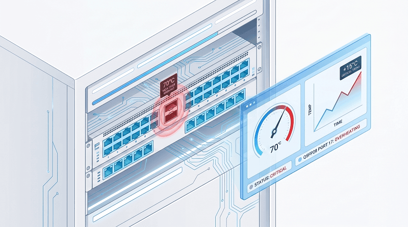
A fully-loaded 32-port QSFP28 switch with LR4 modules hit thermal alarms during a summer heatwave at a site I visited. Ambient crept to 28°C. The switch’s internal sensors tripped at 52°C and started throttling ports. The team had to install row coolers and re-rack with blanking panels to force airflow through the chassis, not around it. The fix worked, but the three-day outage wasn’t on anyone’s project plan.
The thermal cascade follows a predictable pattern:
1. Ambient temperature rises (summer, failed HVAC)
2. Module temperature crosses 70°C threshold
3. Laser auto-shutdown triggers TX Fault
4. Remote end sees RX LOS (Loss of Signal)
5. Switch may mark module as “not supported” if thermal protection corrupts EEPROM reads
What looks like three separate problems — TX Fault, RX LOS, and QSFP28 not recognized — is actually one thermal event cascading through multiple alarms. Check temperature first.
BER Monitoring and Interpretation
QSFP28 100G links use 4 x 25G NRZ electrical lanes for the host interface. This is different from the PAM4 signaling used by many 400G and 800G interfaces. NRZ generally has better noise tolerance than higher-speed PAM4 links, but BER monitoring is still critical.
| BER Reading | Interpretation | Action |
| Pre-FEC < 10⁻⁵ | Healthy link | Monitor baseline |
| Pre-FEC 10⁻⁵ to 10⁻⁴ | Degraded margin | Inspect fiber; check connectors |
| Pre-FEC > 10⁻⁴ | Near failure | Replace module or fiber immediately |
| Post-FEC > 0 | Critical | Link operating beyond correction capacity |
Any increasing post-FEC error trend on a QSFP28 link means your margin is exhausted. The link may stay up, but it’s one noise burst away from flapping.
Phase 5: Isolation Testing
Swap the right component and you’ll know in 30 seconds.
When you’ve ruled out physical, EEPROM, configuration, and signal quality issues, structured isolation testing is the final step in QSFP28 troubleshooting. The goal is to identify whether the fault is in the module, the port, the cable, or the remote end.
The Swap Test Decision Tree
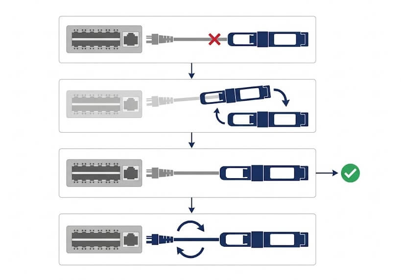
Step 1: Module to known-good port
Move the suspect module to a port that works with a known-good module.
If the suspect module works → original port or cable is the problem.
If the suspect module still fails → module is likely faulty.
Step 2: Known-good module to suspect port
Move a working module to the suspect port.
If it works → original module is faulty.
If it fails → port or cable is the problem.
Step 3: Cable replacement
Replace the cable with a known-good spare.
If link works → cable was the issue.
If link still fails → problem is in the port or module.
Step 4: Remote end swap
If both local tests pass, repeat Steps 1-2 on the remote end.
This four-step sequence isolates the fault in four moves or fewer. Most engineers skip steps or swap multiple components simultaneously, which destroys diagnostic clarity. Patience is a virtue in systematic QSFP28 troubleshooting.
Loopback Module Testing
Loopback modules short the TX lanes back to the RX lanes internally. They’re the fastest way to separate host-side issues from fiber-side issues.
When to use a loopback in QSFP28 troubleshooting:
Link won’t establish and you need to know if the switch port is healthy
Remote site is inaccessible and you need local verification
Suspected host ASIC lane failure
Expected behavior:
Insert loopback, enable port
Port should come up immediately (no fiber needed)
DOM will show high RX power (expected — it’s a short loop)
BER should be near zero
If the port won’t come up with a loopback, the issue is host-side: ASIC, SerDes, electrical interface, firmware, or configuration. If it works with loopback but not with a real module and fiber, the issue is optical, cabling, remote-side, or interoperability-related. Loopback testing is one of the fastest ways to narrow your QSFP28 troubleshooting scope.
QSFP28 Troubleshooting Toolkit
You don’t need a lab full of equipment to diagnose most 100G issues. Here’s what actually matters.
| Tool | Purpose | Approximate Cost | When to Use |
| Fiber inspection microscope (200-400x) | End-face quality check | $150-400 | Phase 1 — every suspected link |
| Optical power meter | Measure actual TX/RX levels | $200-600 | Phase 4 — verify optical budget |
| QSFP28 loopback module | Host-side port verification | $50-100 | Phase 5 — isolate port vs. module |
| Visual fault locator | Fiber continuity check | $30-80 | Phase 1 — find breaks or tight bends |
| Fiber cleaning kit (pen + wipes + fluid) | Connector cleaning | $20-50 | Phase 1 — always, before insertion |
That $5 cleaning pen prevented $12,000 in unnecessary RMAs. Pretty good return.
Pre-Deployment Checklist
The best QSFP28 troubleshooting happens before the link goes down. Run this checklist before every deployment:
- Verify switch firmware supports the specific module type — check vendor release notes
- Confirm FEC settings match on both ends — especially for SR4, CWDM4, and breakout links
- Confirm fiber type and connector match module spec — MMF for SR4, SMF for LR4/CWDM4/ER4
- Inspect and clean all connectors before insertion — every single one
- Document baseline DDM values — temperature, TX/RX power, voltage, and bias current
- Set automated alerts — for example, temperature >65°C, power deviation >3 dB, voltage outside expected range, or increasing post-FEC errors
- Verify compatibility matrix — especially for third-party modules
- Label breakout cables with polarity method — Method A, Method B, Method C, or vendor-specific mapping
Run this checklist and you’ll prevent roughly 70% of the issues that otherwise turn into 2 AM pages.
QSFP28 Troubleshooting FAQ
Why is my QSFP28 not detected?
Check physical seating first, then vendor compatibility. QSFP28 not detected is often a vendor lock issue, not a dead module. Verify the module appears in show interfaces transceiver or your platform’s equivalent. If it shows “unsupported,” check EEPROM vendor coding or enable service unsupported-transceiver on Cisco. Update switch firmware before RMAing modules.
What causes QSFP28 TX fault?
TX Fault usually means the transmitter laser has shut down. Most commonly caused by over-temperature (>70°C), which triggers automatic laser protection. Less commonly caused by laser bias current out of range or incompatible host electrical interface. Check DOM temperature first — it’s the #1 culprit.
How do I clean QSFP28 fiber connectors?
Inspect first with a 200–400x fiber microscope whenever possible. Use an approved fiber cleaning pen, cassette, or wet-to-dry cleaning method with lint-free wipes and approved cleaning fluid. For MPO-12 connectors used by many SR4 modules, use an MPO cleaning tool. For APC connectors, use tools and fluids approved for angled end-faces and avoid solvent residue. Re-inspect before reconnecting.
What DDM values are normal for QSFP28?
Temperature: 35-55°C for SR4, up to 60-68°C for LR4. Voltage: 3.13-3.47V. TX/RX power: within module datasheet spec, with at least 3dB margin above receiver sensitivity. Bias current: stable baseline; a 20% increase indicates end-of-life.
Why does my breakout cable only show 3 of 4 lanes?
Polarity mismatch is the most likely cause. Breakout cables typically use Method B (crossover) polarity. Verify the cable labeling against your switch documentation. Also confirm the port is configured for 4x25G breakout mode and that FEC settings match across all lanes.
Can I use third-party QSFP28 in Cisco switches?
Yes, with correct EEPROM vendor coding. Some switches require the service unsupported-transceiver command. This may affect warranty coverage for that port. Arista is generally more permissive. Third-party modules with proper coding work reliably — the real issue is usually EEPROM compatibility, not hardware quality.
Key Takeaways
Marcus didn’t make the same mistake twice. After his $12,000 cleaning lesson, he built a pre-deployment checklist that caught three more contamination issues before they reached production. His team now resolves most 100G link issues in under 30 minutes.
Here’s what to remember from this QSFP28 troubleshooting guide:
Seventy percent of QSFP28 failures are physical layer. Clean connectors, reseat modules, and check cables before you touch a configuration.
Update firmware before RMAing hardware. Vendor lock and known firmware bugs waste days and shipping costs.
DDM trends predict failures before they happen. Track laser bias current and temperature. Replace modules showing degradation during planned maintenance, not during outages.
Use the swap test decision tree. Swap one component at a time. Simultaneous swaps destroy diagnostic clarity.
Any post-FEC BER is critical. Pre-FEC errors are expected. Post-FEC errors mean your margin is gone.
QSFP28 troubleshooting at 100G is fundamentally about discipline. The modules are mature. The protocols are well-defined. Most failures are predictable once you know the patterns. Master the 5-phase workflow and you’ll spend less time chasing ghosts and more time keeping links stable.
If you need replacement modules, loopback test equipment, or compatibility-verified optics for your QSFP28 troubleshooting toolkit, contact FiberMall. We test every module against major switch platforms before shipment and can pre-code EEPROMs for your specific vendor environment.
For the broader picture on QSFP28 technology — form factors, speeds, and module types — our complete QSFP28 guide covers the fundamentals. And if you’re already running 400G/800G and need parallel troubleshooting guidance, see our QSFP-DD troubleshooting guide.
Related Products:
-
 QSFP28-100G-SR4 100G QSFP28 SR4 850nm 100m MTP/MPO MMF DDM Transceiver Module
$40.00
QSFP28-100G-SR4 100G QSFP28 SR4 850nm 100m MTP/MPO MMF DDM Transceiver Module
$40.00
-
QSFP28-100G-IR4 100G QSFP28 IR4 1310nm (CWDM4) 2km LC SMF DDM Transceiver Module
$110.00
-
QSFP28-100G-DR1 100G QSFP28 Single Lambda DR 1310nm 500m LC SMF with FEC DDM Optical Transceiver
$180.00
-
QSFP28-100G-PSM4 100G QSFP28 PSM4 1310nm 500m MTP/MPO SMF DDM Transceiver Module
$180.00
-
QSFP28-100G-FR1 100G QSFP28 Single Lambda FR 1310nm 2km LC SMF with FEC DDM Optical Transceiver
$215.00
-
Arista Networks QSFP-100G-LRL4 Compatible 100G QSFP28 LRL4 1310nm (LWDM4) 2km LC SMF DDM Transceiver Module
$245.00
-
QSFP28-100G-LR1 100G QSFP28 Single Lambda LR 1310nm 10km LC SMF with FEC DDM Optical Transceiver
$265.00
-
QSFP28-100G-SR1.2 Single Rate 100G QSFP28 BIDI 850nm & 900nm 100m LC MMF DDM Optical Transceiver
$280.00
-
QSFP28-100G-LR4 100G QSFP28 LR4 1310nm (LAN WDM) 10km LC SMF DDM Transceiver Module
$285.00
-
QSFP28-100G-SWDM4 100G QSFP28 SWDM4 850nm-940nm 100m LC MMF DDM Optical Transceiver
$300.00
-
QSFP28-100G-LR4-20 100G QSFP28 LR4 1310nm LWDM4 20km LC SMF DDM Transceiver Module
$300.00
-
QSFP28-100G-BDRX 100G QSFP28 BIDI 850nm & 900nm Only Receiver 100m LC MMF Optical Transceiver
$379.00
-
QSFP28-100G-SRBD Dual Rate 40G/100G QSFP28 BIDI 850nm & 900nm 100m LC MMF DDM Optical Transceiver
$449.00
-
QSFP28-100G-ER1 100G QSFP28 ER1 Single Lambda 1310nm 40km PAM4 LC SMF DDM Transceiver Module
$1250.00