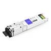
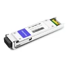
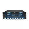
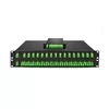
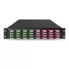
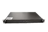
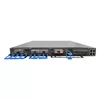
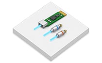
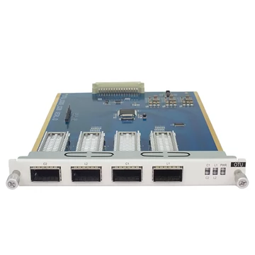
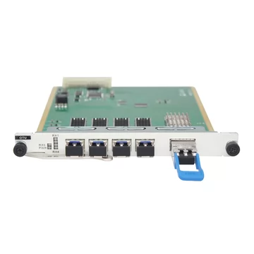
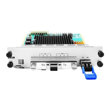
Your switch uses a standard gray optical interface, such as 850 nm or 1310 nm, while your DWDM backbone carries specific ITU-grid wavelengths. Those two interfaces cannot always connect directly. The usual solution is an OEO optical transponder: a device that receives an optical signal, converts it into the electrical domain, processes or regenerates it as required, and retransmits it as a new optical signal at the required wavelength.
This allows existing Ethernet, Fibre Channel, SONET/SDH, and other supported optical interfaces to connect to CWDM or DWDM transport systems without replacing the original network equipment.
What Is an Optical Transponder OEO?
An optical transponder OEO is a signal-conversion device that operates through an optical-electrical-optical signal path. "OEO" stands for optical-electrical-optical: the device receives an optical signal, converts it to an electrical signal, processes the electrical data, and then drives another optical transmitter to retransmit the signal.
Depending on the transponder design, the electrical stage may perform 2R regeneration — re-amplification and re-shaping — or full 3R regeneration, which adds re-timing. The output wavelength is determined by the line-side optical interface or transceiver.
This architecture enables three important functions that passive optical devices cannot provide by themselves.
First, the transponder can perform wavelength conversion, allowing standard gray wavelengths such as 850 nm, 1310 nm, or 1550 nm to be converted to a supported CWDM or DWDM channel.
Second, it can perform signal regeneration. A 3R-capable transponder re-amplifies, re-shapes, and re-times the signal, effectively creating a new optical transmission span instead of simply amplifying the incoming light. However, not every OEO device provides full 3R; some designs operate as 2R regenerators or support 3R only at specific data rates.
Third, depending on the available interfaces and installed transceivers, an OEO platform can also bridge different optical media or interface types, such as multimode to single-mode fiber, or dual-fiber to single-fiber BiDi transmission.
An important point is that many OEO transponders are service- or protocol-transparent within their supported data-rate range. They do not normally convert one network protocol into another. A 10G Ethernet service remains 10G Ethernet, and a Fibre Channel service remains Fibre Channel.
However, "protocol-transparent" does not mean that every OEO transponder supports every protocol or every bit rate. Retiming circuitry, clock recovery, framing functions, and optional OTN/FEC processing can impose specific rate and protocol requirements.
What an OEO Transponder Does
The three core functions of an OEO transponder are:
· Wavelength conversion — Convert a supported gray optical wavelength such as 850 nm, 1310 nm, or 1550 nm into a CWDM or DWDM wavelength so conventional network equipment can connect to a WDM transport system without requiring native WDM optics in the host device.
For DWDM systems, the line-side optical interface normally operates on a channel aligned with the ITU-T G.694.1 frequency grid. CWDM systems use wavelengths defined by ITU-T G.694.2.
· 2R or 3R signal regeneration — Re-amplify and re-shape the signal, and on 3R-capable equipment, re-time it as well. Full 3R regeneration restores the digital signal and allows the next optical segment to begin with a newly generated signal rather than continuing to carry accumulated analog impairments.
· Optical interface and fiber adaptation — Depending on the transponder and installed optics, bridge multimode and single-mode interfaces, different connector or transceiver types, or dual-fiber and single-fiber BiDi transmission.
This is what distinguishes an optical transponder from a basic copper-to-fiber media converter. A conventional media converter primarily changes the physical media or fiber interface, whereas an OEO wavelength transponder is typically used for optical-to-optical conversion, wavelength adaptation, and signal regeneration.
The distinction is not absolute because some fiber media converters can also perform optical-to-optical conversion. In practice, "transponder" is most commonly used when wavelength conversion, WDM integration, regeneration, or transport-network applications are involved.
OEO Transponder vs. Media Converter vs. Muxponder
The naming can be confusing because vendors do not always use these terms consistently. For network design, the following distinction is the most useful.
A media converter primarily converts between physical media or interface types. The most common example is copper-to-fiber Ethernet, although fiber-to-fiber converters are also available for multimode-to-single-mode conversion or other optical interface changes. You typically use a media converter when extending Ethernet beyond the practical reach of copper or when joining incompatible physical media.
An OEO transponder receives an optical client signal and retransmits it through another optical interface. It can perform wavelength conversion and, depending on its architecture, 2R or 3R regeneration. In a WDM network, a common application is converting a gray client interface into a colored CWDM or DWDM line interface. It is also useful for regenerating an optical signal between transmission spans.
A muxponder goes one step further. Instead of carrying only one client signal over one line signal, it aggregates several lower-rate client signals into a higher-rate trunk signal, typically using digital multiplexing such as OTN mapping. At the far end, another muxponder separates the aggregated signal back into the individual client services.
For example, a muxponder may combine several lower-rate client services into one higher-capacity DWDM wavelength.
In simple terms, a transponder is generally one client signal to one line signal, whereas a muxponder handles multiple client signals over an aggregated higher-rate line signal. Cisco uses the same fundamental distinction in its optical transport platforms.
Data Rate and Interface Options
OEO transponders are available across a wide range of data rates. The correct platform depends on the client interface, required regeneration function, and line-side optics.
· 100 Mbps / 1G — SFP-based transponders are available for legacy Ethernet, SONET/SDH, Fibre Channel, and other supported low-rate services. Multi-rate products can be useful when migrating existing low-speed optical links onto CWDM or DWDM infrastructure.
· 10G — One of the most common OEO categories. Depending on the product, interface combinations may include SFP+ to SFP+, SFP+ to XFP, or XFP to XFP. Supported services may include 10 Gigabit Ethernet, 10G Fibre Channel, STM-64/OC-192, OTU2, and other data rates within the transponder's specified operating range.
Many 10G transponders provide full 3R regeneration, but this capability must be confirmed for the specific product and operating mode.
FEC should also not be assumed to be a standard feature of every 10G OEO transponder. Some transport-oriented transponders support G.709 framing and FEC/E-FEC, while simpler protocol-transparent wavelength converters do not. Cisco, for example, documents different transponder operating modes both with and without FEC.
· 40G / 100G — Higher-rate OEO systems may use QSFP+, QSFP28, CFP-family, or other optical interfaces depending on the platform. These products are commonly deployed in data-center interconnect, metro transport, and high-capacity backbone applications.
At these rates, the architecture varies substantially. Some systems provide relatively straightforward optical-to-optical regeneration, while others incorporate OTN framing, FEC, coherent line interfaces, or additional transport functions.
The interface pairing is therefore one of the first things to confirm.
If both sides require SFP+, an SFP+↔SFP+ design may be appropriate. If a legacy XFP interface must connect to an SFP+ system, an SFP+↔XFP transponder may be used if the platform supports the required data rate.
On systems with open pluggable slots, wavelength and optical reach are largely determined by the compatible transceivers installed in those slots. This makes it possible to adapt one OEO platform to different transmission distances and wavelengths without replacing the entire chassis.
However, the transponder itself must still support the electrical line rate, encoding, clocking requirements, and optical module type being used.
Wavelength Conversion: 850/1310/1550 nm to CWDM/DWDM
This is one of the most common reasons to deploy an OEO transponder: converting a standard gray optical interface into a WDM wavelength.
For an 850 nm source, the input is typically a multimode SFP, SFP+, or similar short-reach optic. An OEO transponder can receive this signal and retransmit it through an appropriate single-mode 1310 nm, 1550 nm, CWDM, or DWDM optical interface, provided the transponder supports the required data rate and optics. A common use case is connecting legacy multimode equipment to a single-mode WDM backbone.
For a 1310 nm source, the input is commonly a standard single-mode Ethernet, Fibre Channel, or transport optic. The transponder can terminate the 1310 nm optical signal electrically and retransmit the data through a CWDM or DWDM line-side transceiver. This allows existing gray 1310 nm interfaces to be multiplexed into a WDM system.
For a 1550 nm gray source, the same OEO principle applies. The incoming signal is converted to the electrical domain and then transmitted through the required line-side CWDM or DWDM optical module. This approach can be used to integrate existing long-reach optical interfaces into metro or transport networks.
Because the incoming signal is detected and regenerated in the electrical domain, the output light is generated by the line-side transmitter rather than being optically filtered or shifted from the original carrier.
The output wavelength is therefore determined by the line-side optical transceiver or integrated laser. For DWDM deployment, that line-side transmitter must be compatible with the wavelength or frequency plan of the DWDM system; for CWDM, it must match the required CWDM wavelength.
OEO conversion does not eliminate the need for optical link engineering. Transmit power, receiver sensitivity, insertion loss, dispersion, OSNR, mux/demux loss, amplifier characteristics, and the capabilities of the selected optics still need to be considered.
Standalone, Rack-Mount, or Managed Chassis
OEO transponders are commonly available in three form factors, and the right choice depends primarily on deployment scale and management requirements.
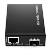
· Standalone mini — A compact desktop or wall-mount unit designed for one or a small number of point-to-point wavelength conversion or regeneration tasks. These products are often plug-and-play and may operate without centralized management.
· 1U/2U rack-mount — A rack-mounted platform that accommodates multiple OEO channels in a single enclosure. It is useful when several wavelength conversions or regeneration links need to be deployed in one cabinet.
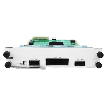
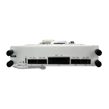
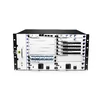
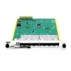
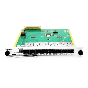
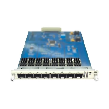
· Managed chassis card — An OEO line card installed in a larger managed optical transport chassis. Depending on the system, management may include Web GUI, SNMP, CLI or console access, alarm monitoring, performance statistics, optical diagnostics, and redundant power.
Standalone equipment is usually suitable for a small number of links. As the number of channels increases, a managed chassis can simplify power distribution, monitoring, maintenance, alarms, and remote troubleshooting.
Technical Specifications
The exact specifications of an OEO transponder vary significantly by product, so the following values should be treated as typical examples rather than universal specifications.
Data rates: OEO platforms are available for rates ranging from sub-Gigabit and 1G services through 10G, 40G, 100G, and higher. A multi-rate transponder supports only the data-rate range specified by its manufacturer.
Protocols: Depending on the model, supported services may include Ethernet, SONET/SDH, Fibre Channel, OTN, CPRI, ESCON/FICON, or other serial optical protocols. Protocol-transparent operation is normally limited to supported bit rates and electrical processing modes.
Functions: Typical functions include wavelength conversion and 2R or 3R regeneration. Some transport-class platforms additionally support OTN framing, FEC, performance monitoring, or protection switching.
Interfaces: Common pluggable interfaces include SFP, SFP+, XFP, QSFP+, QSFP28, CFP-family modules, and other platform-specific optical interfaces. Possible pairings include SFP+↔SFP+, SFP+↔XFP, or XFP↔XFP on compatible 10G equipment.
Wavelengths: Depending on the installed optics, client interfaces can operate at wavelengths such as 850 nm, 1310 nm, or 1550 nm, while line-side interfaces can use CWDM or DWDM wavelengths. DWDM channels should match the applicable system frequency grid, while CWDM channels typically follow the ITU-T CWDM wavelength grid.
Transparency: Many OEO transponders can carry supported client protocols transparently at the service level. Because the signal undergoes O-E-O conversion, however, the device is not optically transparent in the literal sense.
Diagnostics: Depending on the platform and optical modules, functions may include DDM/DOM monitoring, transmit/receive optical power monitoring, temperature and voltage monitoring, alarm reporting, ALS, loopback, and PRBS generation/checking. These features are product-dependent.
Form factor: Common options include standalone mini units, 1U/2U rack-mount systems, and modular cards installed in managed optical transport chassis.
Management: Standalone models may be unmanaged, while managed platforms can provide Web, SNMP, CLI, console, or network-management-system integration.
Power: Power requirements vary considerably by platform. Compact 1G/10G units may consume only several watts per channel, while multi-channel chassis, high-speed transponders, and coherent transport systems require substantially more power. AC and -48 V DC options are commonly available in carrier-oriented equipment.
Operating temperature: Commercial-temperature products commonly operate around 0 to 50 or 70 °C, depending on the design. Industrial or extended-temperature versions may support a wider operating range. The exact temperature specification must be verified from the individual product datasheet.
Frequently Asked Questions
What is an OEO converter / optical transponder?
An OEO converter — also called an optical transponder or wavelength-converting transponder — receives an optical signal, converts it into the electrical domain, and retransmits it through another optical interface.
It is widely used for wavelength conversion, optical interface adaptation, and signal regeneration in CWDM, DWDM, metro, data-center interconnect, and transport networks.
What does optical-electrical-optical (OEO) mean?
OEO describes the signal path: optical input, electrical processing, and optical output.
Converting the incoming signal to the electrical domain allows the device to regenerate or process the data before generating a new optical signal.
Depending on the design, this processing may provide 2R regeneration — re-amplification and re-shaping — or full 3R regeneration, which also includes re-timing.
What is the difference between an OEO converter and a media converter?
A conventional media converter primarily changes the transmission medium or physical interface, such as copper↔fiber or multimode↔single-mode.
An optical OEO transponder works optical-to-optical through an intermediate electrical stage and is commonly used for wavelength conversion and signal regeneration.
The boundary is not absolute because some fiber media converters also perform optical-to-optical conversion, but transponders are more commonly associated with WDM and optical transport applications.
What is a transponder vs. a muxponder?
A transponder typically converts one client signal into one line-side optical signal and performs the reverse conversion at the other end.
A muxponder additionally combines multiple lower-rate client signals into a higher-rate trunk signal, usually using digital multiplexing or OTN mapping.
In short, a transponder is generally one-to-one, while a muxponder is many-to-one on the line side.
What is 3R regeneration?
3R refers to re-amplification, re-shaping, and re-timing.
These operations recover the incoming digital signal and generate a new, clean transmission signal. Because timing is recovered and regenerated, a 3R transponder can remove accumulated amplitude and timing degradation that simple optical amplification cannot correct.
However, not every OEO converter provides 3R. Some devices perform only 2R regeneration, so the product specification should be checked before deployment.
Can an OEO converter change protocols, like 10G SONET to 10G Ethernet?
A standard protocol-transparent OEO transponder does not convert 10G SONET/SDH into 10G Ethernet.
It retransmits the supported incoming service through another optical interface while preserving the client traffic.
Some advanced transport platforms may terminate, encapsulate, map, or process protocols through OTN or other digital functions, but that is beyond basic transparent OEO wavelength conversion.
How do I convert 1310 nm to 1550 nm, or to a CWDM/DWDM wavelength?
Connect the 1310 nm source signal to the client-side port using a compatible receiver or pluggable transceiver.
On the line side, install the required 1550 nm, CWDM, or DWDM optical transceiver.
The OEO transponder receives the original signal, converts it into the electrical domain, and uses the line-side transmitter to generate a new optical signal at the required wavelength.
For CWDM or DWDM applications, the selected output transceiver must match the channel plan, mux/demux, fiber type, optical budget, and transmission requirements of the WDM system.
Can an OEO converter convert multimode to single mode?
Yes, if the transponder supports the required data rate and accepts the appropriate optical modules.
For example, an 850 nm multimode client signal can be received on one side of the OEO transponder and retransmitted through a 1310 nm, 1550 nm, CWDM, or DWDM single-mode optic on the other side.
This makes it possible to connect a legacy multimode segment to a single-mode backbone without replacing the original host equipment. The exact combination still depends on the transponder's supported interfaces, data rates, and transceiver compatibility.