Fiber Optic Loopback Modules: How They Work, Testing Methods, and Selection Guide
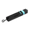
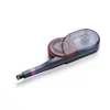
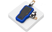
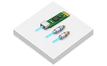
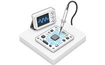
A fiber optic loopback module is a passive testing device that routes an optical transceiver's transmitted signal (Tx) directly back to its receiver (Rx), enabling rapid verification of the transceiver and local port functionality. During equipment troubleshooting, it establishes a local closed-loop optical connection to evaluate the transmit and receive paths without requiring remote equipment. This helps distinguish local transceiver or interface problems from faults elsewhere in the optical link, reducing unnecessary component replacements.
The Cost of a Bad Transceiver Diagnosis
When an optical link fails to come up, a common troubleshooting approach is to replace the transceiver and see whether the problem disappears. This works when the transceiver is actually defective, but wastes time and money when the fault lies elsewhere.
Loopback testing replaces this trial-and-error process with a more systematic diagnostic approach:
- Connect the loopback module: Attach the appropriate loopback device to the transceiver's Tx and Rx optical interfaces.
- If the loopback test passes: The local optical transmit and receive paths are functioning under the tested conditions. The problem may lie in the external cabling, remote equipment, or link configuration.
- If the loopback test fails: The issue may involve the transceiver, local port, loopback connection, optical power levels, or interface configuration. Further testing is needed to isolate the exact cause.
A single test can help prevent a $1,000 transceiver from being returned as defective when the actual problem is a patch panel, a polarity mismatch, or a contaminated connector. For data center and telecommunications teams managing hundreds of optical ports, loopback modules can significantly reduce troubleshooting time and unnecessary equipment replacements.
However, a successful loopback test does not guarantee that a transceiver will operate correctly over its specified transmission distance or under all network conditions. Additional optical power, bit error rate (BER), and link-level testing may still be necessary.
How Fiber Loopback Testing Works
A fiber loopback module is a self-contained passive device that redirects an optical transceiver's transmitted light back into its receiver, creating a local optical test path without requiring a complete end-to-end fiber link.
There are two common types of loopback testing:
1. Internal loopback: Depending on the transceiver and host platform, an internal loopback function may redirect electrical or digital signals within the host interface or transceiver circuitry. This helps verify specific electronic or signal-processing paths but does not necessarily test the optical transmitter and receiver.
2. External loopback: A physical fiber loopback module connects the optical transmitter to the receiver through a short optical path. This allows engineers to evaluate the local optical transmit and receive functions, including the relevant connector interfaces.
Where supported, engineers can perform an internal loopback test first, followed by an external optical loopback test. If the internal test passes but the external test fails, the problem may involve the optical transmitter, receiver, connector interface, fiber mapping, or optical power level. If both tests pass, the local signal paths are functioning under the tested conditions, suggesting that further investigation should focus on the external link or remote equipment.
Internal loopback availability and behavior vary by transceiver architecture, switch platform, and diagnostic implementation. Some devices do not support internal loopback, while others require specific test modes or configuration commands. Likewise, an external optical loopback may not cause the interface to report an operational link without appropriate platform support and configuration.
This is why choosing a compatible loopback module is essential. A single-mode loopback used with multimode optics, or a UPC connector mated to an APC interface, can produce unreliable results or potentially damage the connector end faces.
How to Choose the Right Loopback Module
The most common reasons for an unsuccessful loopback test on a known-good transceiver include connector incompatibility, incorrect fiber type, mismatched connector polish, improper fiber mapping, and unsuitable optical power levels. Work through these four selection criteria before testing.
1. Connector Type
Match the loopback connector to the optical interface being tested. LC and SC loopback configurations are commonly used with duplex optical interfaces, including many SFP, SFP+, and SFP28 transceivers.
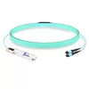
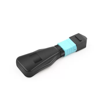
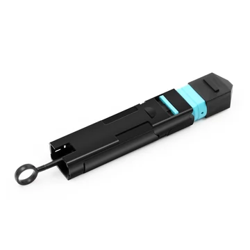
MPO/MTP loopback modules are used with parallel optical interfaces, including certain QSFP+, QSFP28, QSFP-DD, and OSFP transceivers. The required MPO configuration depends on the number and arrangement of active optical lanes. Common configurations include MPO-12, MPO-16, and MPO-24, although not every configuration is suitable for every transceiver.
2. Fiber Mode
Choose the appropriate fiber type based on the transceiver's optical specifications. Single-mode fiber, typically OS2, is commonly used for 1310 nm and 1550 nm applications, while multimode fiber types such as OM3, OM4, and OM5 are commonly used for short-reach 850 nm optical links.
However, wavelength alone does not determine fiber compatibility. Some multimode systems operate at wavelengths other than 850 nm, and single-mode transceivers may use different wavelength ranges.
Using an incompatible fiber type can introduce unexpected insertion loss, modal effects, or unstable test results. Always match the loopback module to the fiber type specified in the transceiver datasheet.
3. Connector Polish
UPC (Ultra Physical Contact) and APC (Angled Physical Contact) connectors are designed with different end-face geometries and must not be directly mated.
UPC connectors feature a polished, slightly convex end face and are widely used in data center and enterprise optical connections. APC connectors use an approximately 8-degree angled end face to reduce back-reflected optical power, making them suitable for applications requiring high return-loss performance.
Blue and green are commonly used to identify single-mode UPC and APC connectors, respectively, although connector colors can vary by product and manufacturer.
4. MPO Polarity and Pinout (Parallel Optics Only)
For parallel optical interfaces, confirm the MPO connector format, active fiber count, connector gender, key orientation, and internal Tx-to-Rx fiber mapping.
MPO cabling commonly uses Type A, Type B, or Type C polarity arrangements, but a loopback module must be selected according to the actual transmit and receive lane assignments of the optical transceiver.
For example, many 40GBASE-SR4 and 100GBASE-SR4 transceivers use an MPO-12 interface with four transmit fibers and four receive fibers. A typical loopback mapping connects positions 1–12, 2–11, 3–10, and 4–9.
Incorrect internal fiber mapping can prevent successful testing even when the loopback connector physically fits the transceiver.
UPC vs. APC and MPO Polarity, Explained
Two connector characteristics frequently cause confusion when selecting fiber optic loopback modules: connector polish and MPO polarity. Understanding these differences helps prevent compatibility issues and misleading diagnostic results.
UPC vs. APC
UPC (Ultra Physical Contact) connectors use a finely polished, slightly convex ferrule end face to establish close physical contact between mating fibers. They are widely used in data center, enterprise, and telecommunications optical connections.
APC (Angled Physical Contact) connectors feature an approximately 8-degree angled ferrule end face that directs reflected light away from the transmitting fiber core, reducing optical back-reflections.
Single-mode UPC connectors commonly achieve return-loss values of 50 dB or higher, while single-mode APC connectors commonly achieve 60 dB or higher under specified testing conditions. Actual performance depends on connector quality, fiber type, and the applicable product specifications.
APC connectors are commonly used in passive optical networks (PON), FTTx infrastructure, and other optical systems sensitive to reflections. Their green connector bodies help distinguish them from the blue connectors commonly associated with single-mode UPC interfaces.
UPC and APC connectors should never be directly mated because their different end-face geometries can cause excessive insertion loss, poor return-loss performance, and connector damage.
MPO Polarity: Type A, B, and C
MPO polarity describes how individual fiber positions are mapped between the ends of a multifiber optical cable. The three commonly used polarity configurations are Type A, Type B, and Type C, as described in the ANSI/TIA-568.3 series of optical fiber cabling standards.
- Type A: A straight-through configuration in which fiber position 1 connects to position 1, position 2 to position 2, and so on. Type A cables generally use a key-up to key-down arrangement.
- Type B: A reversed configuration in which the fiber positions are mapped in the opposite order. For a 12-fiber MPO cable, position 1 connects to position 12, position 2 to position 11, and so on. Type B cables generally use a key-up to key-up arrangement.
- Type C: A pairwise-flipped configuration in which adjacent fiber positions are exchanged, such as positions 1 and 2, 3 and 4, and 5 and 6. Type C cables generally use a key-up to key-down arrangement and are commonly associated with duplex fiber cabling applications.
For a loopback module, the internal fiber routing must connect each active transmit lane to its corresponding receive lane. The correct mapping depends on the transceiver's optical interface rather than simply matching the polarity type of the installed cabling.
For example, a typical MPO-12 loopback for 40GBASE-SR4 or 100GBASE-SR4 applications connects transmit positions 1, 2, 3, and 4 to receive positions 12, 11, 10, and 9, respectively.
Other applications, including SR8 and certain high-density parallel optical interfaces, may require different MPO connector formats and lane mappings.
Therefore, always verify the transceiver's lane assignments and the loopback module's internal fiber mapping before selection.
FiberMall Loopback Modules
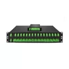
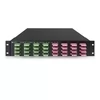
FiberMall loopback modules are designed for optical transceiver testing and troubleshooting in data centers, telecommunications networks, and laboratory environments.
What You Get:
- Comprehensive connector options: LC, SC, FC, ST, and MPO/MTP configurations, including selected 8-, 12-, and 24-fiber arrangements for compatible applications.
- Single-mode and multimode options: Support for OS2 single-mode fiber and multimode fiber types, including OM1, OM2, OM3, OM4, and OM5, depending on the product configuration.
- Multiple connector polish options: PC, UPC, and APC connector finishes for different optical interface requirements.
- Custom attenuation: Optional built-in attenuation for applications that require controlled optical power levels, including receiver testing and selected optical power-budget evaluations.
Typical Specifications (values vary by connector type, fiber type, and product configuration):
Insertion Loss: Typical product specifications may specify insertion loss of ≤0.35 dB for single-mode loopback assemblies and ≤0.40 dB for multimode assemblies. Actual insertion loss depends on the connector configuration, internal fiber routing, and whether attenuation is incorporated.
Return Loss: Single-mode UPC configurations may provide return loss of ≥50 dB, while single-mode APC configurations may achieve ≥60 dB. Multimode configurations may specify return loss of ≥20 dB. These values are representative rather than universal guarantees and should be confirmed against individual product datasheets.
Operating Wavelength: Common single-mode test wavelengths include 1310 nm and 1550 nm, while multimode loopback applications frequently use 850 nm. Other wavelength ranges may be supported depending on the transceiver and fiber configuration.
Connector Durability: Depending on the connector design and manufacturer's specifications, loopback assemblies may be rated for approximately 500–1,000 mating cycles under specified handling and cleaning conditions.
Standards and Testing: Applicable connector and cabling references may include Telcordia GR-326-CORE, the IEC 61754 connector interface series, and the ANSI/TIA-568.3 series. These documents address different aspects of connector performance, interface compatibility, and optical cabling. Compliance should be stated only for the specific standards and requirements verified for each product.
FiberMall loopback modules can be selected according to connector type, fiber mode, optical interface configuration, and application-specific testing requirements.
When testing high-power optical transmitters or sensitive receivers, the returned optical power must remain within the receiver's specified operating range. An attenuated loopback module may be necessary to prevent receiver overload or damage.
Frequently Asked Questions
What is a fiber loopback module?
A fiber loopback module is a passive optical testing device that routes a transceiver's transmitted optical signal back into its receiver. It creates a local optical test path, allowing engineers to evaluate the transceiver and port functionality without connecting to remote equipment.
How do I test a fiber transceiver with a loopback module?
Select a loopback module that matches the transceiver's connector type, fiber mode, polish, and required Tx-to-Rx mapping. Connect it to the optical interface, verify that the returned optical power is within the receiver's supported range, and run the appropriate loopback test supported by the host equipment.
Check the interface status, diagnostic readings, or test results as applicable. A successful test indicates that the local optical path is functioning under the tested conditions. If the test fails, investigate the transceiver, connector, loopback module, port configuration, and optical power levels.
What's the difference between UPC and APC loopback modules?
UPC connectors feature a finely polished, slightly convex end face, while APC connectors use an approximately 8-degree angled end face to reduce optical back-reflections.
Single-mode UPC connectors commonly provide return loss of ≥50 dB, while APC connectors commonly provide ≥60 dB under specified conditions. They are not interchangeable, and the connector polish must match the optical interface being tested.
What is MPO polarity and which type do I need?
MPO polarity defines how individual fiber positions are connected between multifiber interfaces. Common cabling configurations include Type A (straight-through), Type B (reversed), and Type C (pairwise-flipped).
For loopback testing, the most important requirement is that each transmit lane connects to the correct receive lane according to the transceiver's optical interface specification.
For example, many 40GBASE-SR4 and 100GBASE-SR4 transceivers use a reversed Tx-to-Rx mapping across an MPO-12 interface. Always verify the transceiver's lane assignments and the loopback module's internal mapping before ordering.
What insertion loss and return loss should a loopback module have?
For standard non-attenuated single-mode loopback assemblies, representative specifications may include insertion loss of ≤0.35 dB and return loss of ≥50 dB for UPC connectors or ≥60 dB for APC connectors.
For multimode assemblies, representative specifications may include insertion loss of ≤0.40 dB and return loss of ≥20 dB.
Actual performance depends on connector type, fiber configuration, internal routing, and manufacturing quality. Attenuated loopback modules intentionally introduce additional optical loss and should be evaluated according to their specified attenuation values.
Do you offer custom attenuation or OEM loopback modules?
Yes. FiberMall offers loopback module solutions with configurable attenuation values and OEM options, including customized branding, labeling, and packaging for distributors and system integrators. Available configurations and attenuation ranges should be confirmed based on the application requirements.