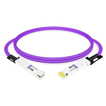
400G DAC Cable Guide: Types, Specs, and Deployment for Data Centers
If you are designing a 400G data center network, you have probably faced the same decision. Optical transceiver modules dominate the conversation, yet direct attach copper remains the most cost-effective interconnect for short-reach links. The challenge is knowing when 400G DAC cables are appropriate, which type to select, and how to avoid the compatibility and signal integrity issues that can derail deployments.
What Is a 400G DAC Cable?
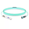
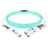
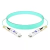
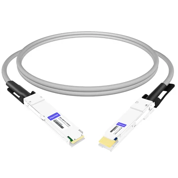
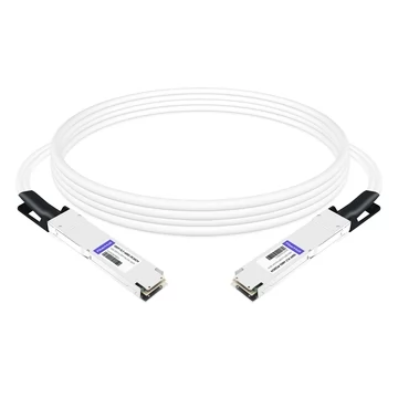
A 400G DAC (Direct Attach Copper) cable is a fixed-length, shielded copper assembly with integrated connectors on both ends. It carries electrical signals directly between two ports without converting them to light. This eliminates the need for separate optical transceiver modules and fiber optic cables, making DAC the simplest and lowest-power option for short-distance 400G connectivity.
Modern 400G DAC cables typically use 8 lanes of 50G-class PAM4 signaling, often described as 8×50G or 8×53.125 Gb/s line rate depending on the interface and encoding. Together, these lanes deliver an aggregate Ethernet data rate of 400 Gbps. The cable itself consists of high-purity copper twinax conductors surrounded by shielding that minimizes crosstalk and electromagnetic interference. Because the signal stays in the electrical domain, passive DAC introduces no optical conversion delay and draws virtually no power beyond EEPROM and management functions.
The connectors on a 400G DAC cable are typically either QSFP-DD (Quad Small Form-factor Pluggable Double Density) or OSFP (Octal Small Form-factor Pluggable). Both form factors support 8-lane high-speed electrical architectures for 400G, but they are mechanically different and are not physically interchangeable. They differ in size, thermal design, ecosystem adoption, and backward compatibility. We will examine those differences in detail later.
400G DAC implementations are commonly aligned with the 400GBASE-R architecture defined in IEEE 802.3bs, related IEEE electrical interface specifications, and 400GBASE-CR8/KR8 copper interface work, along with the mechanical and management specifications published by the QSFP-DD MSA and OSFP MSA. This standardization helps MSA-compliant cables work across switches and network interface cards from different vendors, provided the host equipment supports the correct form factor, port profile, FEC mode, and cable coding.
400G DAC Types and Form Factors
Not all 400G DAC cables serve the same purpose. The right choice depends on distance, power budget, port configuration, and the hardware you already own.
Passive DAC
Passive 400G DAC cables contain no active signal-conditioning electronics. They are shielded copper twinax assemblies with integrated connector housings. The host switch or NIC generates the electrical signal, and the copper conductors carry it directly to the receiving device.
Because there is no signal conditioning inside the cable, passive 400G DAC reach is limited by insertion loss, crosstalk, return loss, and the available SerDes margin on the host ports. In practice, most passive 400G DAC cables support distances from 0.5 meters to 3 meters. Attempting to use a passive DAC beyond its rated length typically results in elevated pre-FEC bit error rates, unstable links, or a complete failure to establish a link.
Power consumption is negligible. A passive 400G DAC typically draws less than 0.1 watts per end, mainly for EEPROM and management functions. This preserves switch ASIC power budgets and reduces cooling load. For this reason, passive DAC is the default choice for intra-rack and top-of-rack links where devices sit within a few meters of each other.
Cable gauge matters. Thicker 26 AWG copper offers lower insertion loss and can support slightly longer distances, but the cable is heavier, stiffer, and harder to route in dense cabinets. Thinner 30 AWG cables are more flexible and easier to manage, but they sacrifice some signal margin. Most 400G DAC cables in the 2-meter to 3-meter range use 26 AWG or 28 AWG to maintain adequate signal integrity.
Active DAC (ACC / AEC)
Active 400G copper cables embed signal-conditioning circuitry inside the connector housing. These chips compensate for copper channel loss through equalization, pre-emphasis, amplification, or retiming, depending on the cable design. The result is a cable that can reliably span longer distances than passive DAC, commonly from 3 meters to 7 meters, with some active copper variants reaching up to 10 meters depending on platform support and cable implementation.
You will see active copper cables marketed as ACC (Active Copper Cable) or AEC (Active Electrical Cable). These terms are related but not always identical. ACC usually refers to copper cables with analog equalization or signal conditioning, while AEC may include retiming, CDR, or more advanced DSP functions. AEC designs generally provide stronger signal recovery and better reach, but they may also consume more power, add slightly more latency, and cost more than simpler ACC designs.
Active copper cables consume more power than passive DACs. Simple ACC designs may remain below about 1 watt per end, while retimed AEC designs can consume more depending on length, lane rate, and vendor implementation. Even so, active copper usually consumes less power than AOC or discrete optical transceiver modules.
Use an active DAC or active copper cable when you need to connect devices in adjacent racks or when a passive cable cannot quite reach the required distance. The cost premium over passive DAC is moderate, usually around 1.5× to 2×, while remaining substantially cheaper than AOC or discrete optics.
Breakout DAC Configurations
Breakout DAC cables split one high-speed port into multiple lower-speed ports. This is useful when connecting a 400G spine switch to existing 100G or 200G leaf infrastructure.
The most common breakout configurations include 400G QSFP-DD to 2×200G QSFP56, which connects one 400G port to two 200G devices and is useful when migrating leaf switches to 200G while the spine runs at 400G. Another common option is 400G QSFP-DD to 4×100G QSFP28, which connects one 400G port to four 100G devices and helps extend the life of legacy 100G leaf switches during a gradual upgrade. OSFP breakout cables are also used in AI and HPC environments, including 400G OSFP to 2×200G or 4×100G breakout configurations, depending on the switch platform, cable SKU, and peer device form factor.
Not all switches support every breakout mode natively. Port profiles, switch ASIC capabilities, firmware versions, and operating system configuration determine whether a 400G port can be split and which breakout configurations are supported. Always verify the switch documentation and vendor compatibility matrix before ordering breakout DAC cables.
QSFP-DD vs. OSFP for DAC
The choice between QSFP-DD and OSFP is not just about optical transceiver modules. It directly affects your DAC strategy as well.
QSFP-DD is smaller, measuring approximately 18.35 mm wide and 8.5 mm high. It was designed to preserve compatibility with the existing QSFP mechanical envelope while doubling the number of high-speed electrical lanes. OSFP is larger, measuring approximately 22.5 mm wide and 13.0 mm high. It was designed with more thermal headroom and a forward-looking 8-lane architecture for 400G, 800G, and beyond. Depending on cage design, cooling architecture, and switch platform layout, modern 1RU switches can support high-density QSFP-DD or OSFP front-panel configurations, although some OSFP systems use slightly lower port counts to prioritize airflow and thermal performance.
For DAC deployments, the most important distinction is backward compatibility. QSFP-DD cages are mechanically backward-compatible with QSFP-family modules such as QSFP28 and, where supported by the host, QSFP56. This means you can install a 400G QSFP-DD switch today and plug in existing 100G QSFP28 DACs where 400G is not yet needed. However, physical fit does not guarantee operational compatibility. Actual operation depends on the switch ASIC, port profile, firmware, FEC mode, cable EEPROM coding, and vendor compatibility policy.
OSFP ports do not natively accept QSFP28 or QSFP56 DACs because the mechanical form factor is different. Adapters may be available in some cases, but they add cost, bulk, insertion loss considerations, and another potential point of failure. For environments with a large installed base of QSFP28 or QSFP56 DACs, QSFP-DD usually provides a smoother migration path.
QSFP-DD remains widely used in general-purpose 400G data center switches, while OSFP is especially common in high-power AI, HPC, and 800G-oriented platforms. In NVIDIA-based AI and GPU cluster environments, both OSFP and QSFP112 variants may appear depending on the NIC, DPU, switch, and generation. Cable selection must therefore match the exact port type rather than assuming one form factor across the entire cluster. Our QSFP-DD vs. OSFP comparison breaks down the full technical and ecosystem differences.
Performance Specifications and Signal Integrity
At 400G, every millimeter of copper and every decibel of insertion loss matters. Understanding the performance boundaries of 400G DAC cables helps you avoid link failures and unstable connections.
Insertion Loss and Signal Margins
400G PAM4 signaling is far less forgiving than the NRZ modulation used in earlier 100G architectures. PAM4 encodes two bits per symbol, which reduces the signal-to-noise ratio and shrinks the voltage eye opening. On copper, this means insertion loss budgets are tight.
Typical passive 400G DAC insertion loss varies by cable length, gauge, connector design, and host channel quality. Longer and thinner cables introduce more loss, while thicker conductors provide better margin at the cost of flexibility. The host SerDes must recover the signal despite this attenuation. Active copper extends the usable range by compensating for channel loss inside the connector, but even active copper has limits. Once the total channel loss exceeds what the host and cable electronics can correct, the link will become unstable or fail.
Pre-FEC BER Thresholds
A healthy PAM4 link should maintain a low pre-FEC bit error rate before Forward Error Correction is applied. As a practical guideline, many operators expect a stable 400G link to maintain pre-FEC BER around 1×10^-6 or better. Values approaching 1×10^-5 require attention because the link is relying more heavily on FEC correction. Values near or above 1×10^-4 may exceed the correction margin of the deployed FEC scheme, depending on the platform, FEC type, and implementation.
The exact threshold is not universal. Different switch ASICs, NICs, SerDes generations, FEC modes, and vendor firmware versions may report and tolerate errors differently. For production deployments, always compare pre-FEC BER, post-FEC error counters, lane-level error distribution, and vendor-recommended thresholds rather than relying on a single number.
Latency
Passive 400G DAC adds virtually no latency beyond the propagation delay through copper, which is approximately 4 to 5 nanoseconds per meter. Active copper adds a small amount of processing delay, depending on whether the cable uses simple equalization, amplification, or retiming. In most data center switching applications, this delay is negligible compared with switch forwarding, queuing, and buffering delays.
AOC latency is also low for most data center applications, but it depends on the internal CDR, DSP, or retimer design. For latency-sensitive deployments such as HPC fabrics, financial trading networks, or tightly synchronized GPU clusters, latency should be checked in the vendor datasheet rather than assumed.
Bend Radius and Thermal Considerations
400G DAC cables, especially those using 26 AWG copper, are thick and stiff. Minimum bend radius is typically in the 35 mm to 55 mm range, depending on gauge and vendor specification. Violating this specification can create impedance discontinuities that degrade signal integrity and increase error rates.
Dense bundles of thick copper cables can also obstruct airflow in high-density switches. In extreme cases, large DAC bundles may raise switch inlet temperatures and force fans to run faster, increasing power consumption and acoustic noise. This does not mean DAC should be avoided, but it does mean cable routing, bundle size, front-to-rear airflow, and serviceability should be considered during rack design.
400G DAC vs. AOC: When to Choose Which
The decision between 400G DAC and 400G AOC (Active Optical Cable) comes down to distance, power, cost, cable management, and environmental conditions.
A passive 400G DAC uses copper twinax and is best suited for same-rack or top-of-rack links. Its typical reach is 0.5 meters to 3 meters. It has the lowest cost, the lowest power consumption, and the lowest latency, but it is thicker and heavier than fiber-based solutions. It is also more sensitive to bend radius, insertion loss, and electromagnetic interference.
An active 400G DAC or active copper cable also uses copper twinax, but it includes signal-conditioning electronics. It is commonly used for 3-meter to 7-meter links, and some variants can reach longer distances depending on the platform and cable design. It costs more and consumes more power than passive DAC, but it is still usually cheaper and lower-power than optical alternatives. Active copper is a good choice when a passive cable cannot quite reach the required distance but fiber is not yet necessary.
A 400G AOC uses multimode fiber with integrated optical engines at both ends. It typically supports longer reaches, often from 30 meters to 100 meters depending on the product. AOC cables are thinner, lighter, easier to route, and immune to electromagnetic interference. However, they consume more power than DAC and cost more than passive or active copper. AOC is often the better choice for rack-to-rack connections, dense cable bundles, or environments where airflow and cable flexibility are more important than the lowest unit cost.
For intra-rack connections under 3 meters, passive 400G DAC is almost always the right choice. It offers the lowest cost, lowest power, and lowest latency. Move to active copper only when you need to stretch a few extra meters between adjacent racks without paying for fiber. Choose AOC when distances exceed the practical reach of copper, when cable density and airflow are critical, or when electromagnetic interference is a concern.
Deployment Scenarios and Selection Guidance
Top-of-Rack Server-to-Switch Links
Top-of-Rack is the classic 400G DAC use case. Servers and storage arrays in the same rack connect directly to the ToR switch. Distances are typically 1 meter to 2 meters. Passive DAC handles these links at the lowest possible cost and power.
Intra-Rack Storage Networking
All-flash storage arrays and NVMe-oF targets often require 400G connectivity to the fabric. When the storage device and switch sit in the same cabinet, a passive 400G DAC cable provides the necessary bandwidth without the cost or complexity of optics.
AI and HPC GPU Cluster Fabrics
AI training clusters with NVIDIA GPUs and high-speed NICs frequently use copper cables for intra-node and intra-rack connections. In these environments, OSFP, QSFP-DD, and QSFP112 may all appear depending on the switch, NIC, DPU, and generation. NVIDIA GPU fabrics often have strict cable management requirements, including supported cable lengths, bend radius, routing path, and airflow rules. Always follow the exact cable and platform guidance for the specific GPU system rather than assuming all 400G copper cables are interchangeable.
Leaf-Spine Uplinks
Leaf-spine uplinks sometimes exceed the reach of passive DAC, particularly in large facilities where leaf and spine switches sit in different racks. Evaluate the physical distance carefully. If the run is under 3 meters, passive DAC provides the best cost efficiency. If it is 3 meters to 7 meters, an active copper cable may bridge the gap. Beyond the practical reach of active copper, AOC or discrete optical transceiver modules are usually necessary.
Breakout Deployments for Legacy Infrastructure
During a phased upgrade, a 400G spine switch may need to connect to existing 100G or 200G leaf switches. Breakout DAC cables allow a single 400G port to fan out to multiple lower-speed ports. This preserves investment in legacy hardware while enabling higher spine capacity. Before deployment, verify lane mapping, port breakout support, FEC compatibility, cable EEPROM coding, and the supported breakout mode on both ends.
Troubleshooting Common 400G DAC Issues
Even a properly specified 400G DAC can fail to establish a stable link. The following workflow addresses the most common field issues.
When Marcus, a network engineer at a European AI lab, deployed 400G DAC cables between NVIDIA DGX systems and a spine switch, three of forty links showed intermittent flapping. The ports would come up, pass traffic for several minutes, then drop. The switch logs showed repeated FEC correction bursts.
Marcus started with the physical layer. He reseated each cable, verified that the latches clicked fully into place, and inspected the connector contacts for contamination. Two of the three cables had minor dust accumulation on the gold-plated pads. After cleaning with isopropyl alcohol and compressed air, those links stabilized.
The third cable was different. Reseating and cleaning had no effect. Marcus checked the pre-FEC BER on the switch CLI and found that it was higher than the expected range for a stable production link. He swapped the suspect cable with a known-good spare from a working port. The issue followed the cable, confirming a defect or signal integrity issue in the cable assembly. The RMA replacement resolved the problem.
Structured Troubleshooting Checklist
Verify physical installation. Reseat the cable and confirm that the latch engages fully. Inspect connector contacts for dust, oxidation, or damage.
Check bend radius. Ensure the cable bend stays within the vendor-specified minimum bend radius, typically around 35 mm to 55 mm depending on gauge.
Review port configuration. Confirm that speed, breakout mode, FEC mode, and lane configuration match on both ends.
Monitor error counters. Check CRC, FCS, symbol errors, pre-FEC BER, post-FEC errors, and lane-level error distribution. Look for lane imbalance across the PAM4 lanes.
Perform a swap test. Move the suspect cable to a known-good port, or move a known-good cable to the suspect port. This isolates cable issues from port or host issues.
Verify firmware and compatibility. Confirm that the switch and NIC firmware support the DAC part number, EEPROM coding, CMIS or SFF management interface, and cable length.
Check thermal conditions. Monitor switch inlet temperature and fan behavior. Dense DAC bundles can restrict airflow and contribute to thermal stress.
Inspect breakout mappings. In breakout configurations, verify lane mapping consistency and confirm that all downstream ports use matching speed and FEC settings.
Cost Analysis and TCO Considerations
For procurement teams, the cost difference between 400G interconnect options is substantial.
Typical third-party passive 400G DAC pricing may range from approximately $50 for a short 0.5-meter cable to around $85 or more for a 3-meter cable, depending on coding, vendor, length, gauge, and certification requirements. Active DAC or active copper usually carries a 1.5× to 2× premium over passive DAC. In contrast, a pair of 400G optical transceivers plus a fiber optic patch cable can cost roughly $2,000 to $3,000 per link, depending on module type and vendor. AOC cables sit in the middle, typically around $300 to $600 depending on length and specification.
The upfront savings are obvious, but the total cost of ownership extends beyond the purchase price. Passive 400G DAC draws less than 0.1 watts per end, while active copper, AOC, and optical transceiver modules consume more power. Over thousands of ports, this power difference translates into measurable reductions in electricity and cooling costs.
However, there is a caveat. In extremely dense cabinets, thick copper bundles can obstruct airflow. The resulting thermal impact may increase fan power, reduce serviceability, and place additional stress on switch cooling systems. For most standard data center densities, this effect is manageable with good cable routing. For ultra-dense AI clusters with thousands of 400G links, cable management and airflow modeling should factor into the TCO calculation.
Use 400G DAC for links under 3 meters where the cost savings are clear and airflow is manageable. For longer runs or high-density environments where cable bulk becomes a problem, AOC may deliver better TCO despite the higher unit price.
Future Outlook: From 400G DAC to 800G
The transition to 800G is already underway in hyperscale networks. Understanding how 400G cable choices affect 800G migration helps you avoid stranded investments.
800G signaling commonly uses 100G-class or 112G-class PAM4 electrical lanes, depending on the architecture and form factor. This is significantly more demanding on copper than 400G’s 50G-class PAM4 lanes. As a result, passive 800G DAC reach is generally shorter than passive 400G DAC reach, often around 2 meters or less depending on cable gauge, host channel quality, and platform support. Active copper cables, including ACC and AEC variants, can extend this reach, but the physics of copper at higher lane rates are unforgiving.
This means data centers planning an 800G upgrade within the next two to three years should evaluate whether their current cable infrastructure will remain useful. If your 400G links are already at the edge of passive DAC reach, you will likely need active copper, AOC, or optical transceiver modules when upgrading to 800G.
Form factor choices also matter. QSFP-DD800 supports 800G and provides a familiar migration path for environments already using QSFP-DD 400G. OSFP supports 800G natively and is widely used in AI and HPC platforms where thermal headroom is critical. If you are building an AI cluster today, OSFP may provide a cleaner upgrade path in some ecosystems, while QSFP-DD may offer better continuity for general-purpose data center networks with existing QSFP-family investments.
For general-purpose data centers, the pragmatic approach is to deploy 400G DAC where it makes sense today while reserving fiber infrastructure for links that will likely need optical speeds, longer reach, or higher-density cable management in the near future.
Conclusion
400G DAC cables remain the most efficient way to connect devices over short distances in modern data centers. They deliver 400 Gbps at a fraction of the cost of optical transceiver modules, with negligible power draw and near-zero cable latency. The key is matching the right cable type to your deployment scenario.
Use passive 400G DAC for intra-rack and top-of-rack links under 3 meters. Choose active copper when you need to reach adjacent racks up to roughly 7 meters, depending on platform and cable support. Select breakout configurations to bridge 400G spine switches with legacy 100G or 200G leaf infrastructure. Always verify EEPROM coding, CMIS or SFF management compatibility, port profile, FEC mode, firmware support, and the vendor compatibility matrix before deploying at scale.
When distances grow or cable density becomes critical, AOC and optical transceiver modules are the logical next step. The goal is not to use DAC everywhere, but to use it where it delivers the best value.