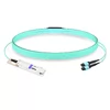
40G Breakout AOC: QSFP+ to 8xLC Cable Guide
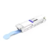
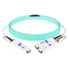
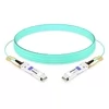
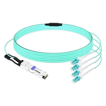
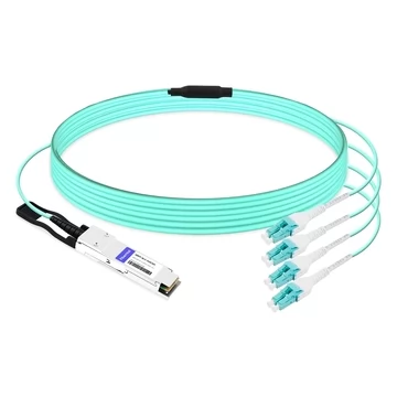
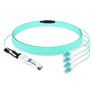
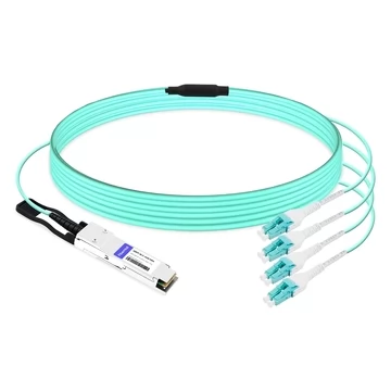
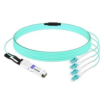
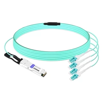
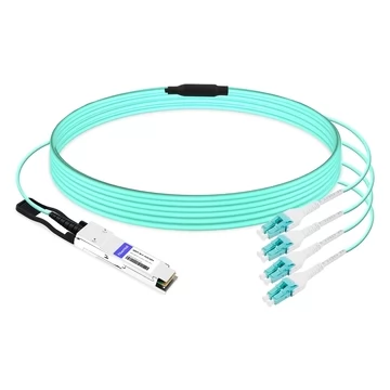
A 40G breakout AOC divides one breakout-capable 40G QSFP+ port into four independent 10G optical links. It has one QSFP+ connector on the switch side and eight individual LC connectors on the opposite side. The eight LC connectors are arranged as four duplex LC pairs, with each pair carrying one 10G transmit-and-receive link.
This architecture improves front-panel port utilization and simplifies connections between a 40G aggregation, leaf, or top-of-rack switch and four 10G devices.
The LC ends are passive fiber terminations rather than electrical SFP+ connectors. Therefore, each remote device must have a compatible integrated 10G optical interface or, more commonly, a 10GBASE-SR SFP+ transceiver.
One 40G Breakout AOC, Four Independent 10G Links
A 40G QSFP+ to 8xLC breakout AOC integrates a QSFP+ optical engine, eight strands of multimode fiber, and eight LC connectors into one factory-terminated assembly.
The QSFP+ interface contains four electrical lanes. When the switch port is configured for 4×10G breakout mode, the operating system exposes four independent 10G logical interfaces rather than one 40G interface.
Each 10G channel uses one transmit fiber, one receive fiber, one duplex LC pair, and one corresponding 10G logical interface. The complete cable therefore contains eight fibers: four transmit fibers and four receive fibers.
Breakout operation is not supported on every QSFP+ port. The switch model, physical port, line card, and software version must all support 40G-to-4×10G channelization.
Key Benefits
Higher port density
One QSFP+ port provides four independent 10G interfaces, reducing the number of front-panel ports required on the 40G switch side.
Simplified rack cabling
The integrated assembly replaces a separate QSFP+ SR4 transceiver, MPO-to-LC breakout harness, and multiple switch-side fiber components.
Direct duplex LC connectivity
Four duplex LC pairs connect directly to four compatible 10G optical interfaces without requiring an MPO cassette or a separate MPO breakout cable.
Lower cable weight
The multimode fiber assembly is lighter and less bulky than a four-lane copper breakout cable, helping reduce cable-tray congestion and airflow obstruction.
Hot-pluggable installation
The QSFP+ end can be installed or replaced without powering down the switch, subject to the normal operating procedures of the network platform.
Platform-specific coding
The QSFP+ EEPROM can be coded for selected Cisco, Arista, Juniper, Dell, HPE, NVIDIA/Mellanox, Brocade, Extreme, H3C, F5 Networks, and other platforms. Compatibility must still be verified against the exact switch model, physical port, and software version.
How the 4×10G Optical Architecture Works
A 40G QSFP+ interface uses four electrical lanes operating at approximately 10.3125 Gb/s each for 40 Gigabit Ethernet.
Inside the QSFP+ end of the cable, the four electrical transmit lanes are converted into four separate 850 nm optical signals. These signals travel over four multimode fibers toward the LC breakout ends.
In the opposite direction, another four fibers carry optical signals from the remote 10G devices back to the four receivers inside the QSFP+ module.
The eight individual LC connectors are grouped into four duplex pairs:
LC pair 1 carries 10G channel 1.
LC pair 2 carries 10G channel 2.
LC pair 3 carries 10G channel 3.
LC pair 4 carries 10G channel 4.
The remote end normally requires four compatible 10GBASE-SR SFP+ transceivers. The cable does not convert a passive electrical SFP+ port into an optical interface by itself.
After the QSFP+ port is configured for breakout mode, the switch normally displays four separate 10G logical interfaces. The exact interface names depend on the switch operating system.
Why Use a QSFP+ to 8xLC Breakout Design?
The main advantage of a 40G breakout AOC is port consolidation on the QSFP+ switch side.
Without breakout, connecting four 10G devices normally requires four SFP+ ports on the aggregation switch, four aggregation-side SFP+ transceivers, four duplex fiber connections, and four remote-side SFP+ transceivers.
With a QSFP+ to 8xLC breakout AOC, the aggregation side instead uses one breakout-capable QSFP+ port, one integrated QSFP+ optical end, one pre-terminated eight-fiber cable assembly, four duplex LC connections, and four remote 10G optical interfaces.
The design does not eliminate the need for compatible optics at the remote devices. Its primary benefits are reducing switch-side port consumption, eliminating the separate QSFP+ SR4 module and MPO breakout harness, and simplifying cable management.
Production-Ready Specifications
A 40G QSFP+ to 8xLC breakout AOC uses one hot-pluggable QSFP+ optical connector at the switch end. The breakout end contains eight individual LC connectors arranged as four duplex LC pairs.
The cable supports an aggregate data rate of 40 Gb/s through four independent 10G channels. For 40 Gigabit Ethernet applications, each electrical lane operates at approximately 10.3125 Gb/s.
The optical system uses four parallel transmit lanes and four parallel receive lanes. Each lane typically operates at 850 nm using VCSEL technology over integrated OM3 multimode fiber.
Common listed cable lengths include 1.5 m, 3 m, 5 m, 10 m, 15 m, 20 m, and 30 m. Custom lengths may be available, but they should be confirmed before being included in a project specification.
The QSFP+ end typically operates within Power Level 1, with maximum power consumption below 1.5 W. The eight LC connectors are passive optical terminations and do not require an electrical power supply.
The typical commercial operating temperature range is 0°C to 70°C. OFNP-rated cable jackets may be available for data center and plenum installations.
The minimum bend radius depends on the exact cable construction, but some versions support a bend radius of approximately 7.5 mm. Installers should always follow the product datasheet and avoid pulling, twisting, or sharply bending the cable.
The cable is intended for 40GbE-to-4×10GbE breakout applications and is based on the four-lane optical architecture associated with 40GBASE-SR4. Relevant specifications may include IEEE 802.3ba, the QSFP+ MSA, and SFF-8436 or related QSFP management and interface specifications.
Exact specifications may vary according to cable length, compatibility coding, product revision, operating environment, and customer requirements.
40G Breakout AOC vs DAC and Discrete Optics
Several cable and optical solutions can divide one 40G port into four 10G connections. The best choice depends on distance, cable weight, port type, installation flexibility, and whether the remote devices already have optical transceivers.
QSFP+ to 8xLC 40G Breakout AOC
A QSFP+ to 8xLC breakout AOC is suitable for direct connections from one 40G switch port to four LC-based 10G optical interfaces.
Its main advantages are the integrated QSFP+ optical engine, clean LC fan-out, low cable weight, and elimination of a separate MPO breakout harness. However, the four remote devices normally still require compatible SFP+ SR transceivers.
QSFP+ to 4×SFP+ Breakout AOC
A QSFP+ to 4×SFP+ breakout AOC has one active QSFP+ connector and four active SFP+ connectors.
Because the optical engines are integrated at both ends, separate transceivers are not required. This option is convenient for direct switch-to-switch, switch-to-server, or switch-to-storage connections. Its main limitation is that both connector types and cable length are fixed.
QSFP+ to 4×SFP+ Passive DAC
A passive DAC breakout cable is usually the most economical option for very short in-rack connections.
It consumes little or no additional optical power and does not require separate transceivers. However, copper breakout cables are heavier, less flexible, and generally limited to approximately 1–5 m, depending on cable gauge and host requirements.
QSFP+ SR4 Transceiver with MPO-to-4×LC Harness
A separate QSFP+ SR4 transceiver and MPO-to-4×LC harness is suitable for structured cabling systems and installations that require replaceable components.
This design provides greater flexibility because the transceiver, trunk cable, cassette, and patch cords can be replaced independently. However, it introduces more components and greater installation complexity.
A standard 40GBASE-SR4 transceiver typically supports up to 100 m over OM3 multimode fiber and up to 150 m over OM4 multimode fiber. Longer distances require an extended-reach optical implementation such as CSR4 or eSR4.
Four Independent SFP+ SR Links
Four separate SFP+ SR links are suitable for switches that do not have a breakout-capable QSFP+ port.
The design is familiar and easy to troubleshoot, but it consumes four switch-side SFP+ ports and four switch-side transceivers. It also requires four duplex fiber connections, just like the breakout system.
8xLC vs Four Duplex LC: What Is the Difference?
The descriptions “8xLC” and “four duplex LC pairs” refer to the same breakout-end configuration.
The term 8xLC counts every individual LC connector. There are four transmit connectors and four receive connectors, for a total of eight individual LC connectors.
The term four duplex LC pairs groups the connectors according to the four 10G links. Each 10G link requires two LC connectors: one for transmission and one for reception.
For customer-facing product descriptions, the clearest terminology is:
40G QSFP+ to 8xLC Active Optical Breakout Cable
One QSFP+ to Four Duplex LC Pairs
This wording retains the searchable product name while explaining the physical configuration accurately.
Choosing the Right Cable Length
Unlike a modular SR4 transceiver system, a 40G breakout AOC is supplied as a factory-terminated assembly with a fixed cable length. The buyer should select the length according to the actual cable-routing path rather than only the straight-line distance between the devices.
Lengths from 1.5 m to 3 m are generally suitable for equipment installed in the same rack.
A 5 m cable can be used in a large rack or for equipment positioned close together.
A 10 m cable is often suitable for connections between adjacent racks.
Lengths from 15 m to 20 m can support row-level connections where the cable must travel through overhead or underfloor pathways.
A 30 m cable may be appropriate for longer routes within a data hall.
When calculating the required length, include vertical routing inside the rack, overhead or underfloor cable trays, service loops, rack-to-rack pathway changes, minimum bend-radius requirements, and additional cable needed for maintenance access.
Excessive slack can obstruct airflow and complicate cable management. However, an optical cable should never be installed under tension.
Where Data Center Teams Deploy It
Aggregation-to-Leaf Connections
One breakout-capable 40G aggregation port can connect to four 10G leaf or access-switch uplinks.
This design is useful when the aggregation platform provides QSFP+ ports but the downstream switches continue to use 10G SFP+ uplinks.
Top-of-Rack to Servers
A 40G QSFP+ port on a top-of-rack switch can provide four 10G connections to servers equipped with compatible SFP+ SR optical interfaces.
This allows one high-density switch port to serve four separate servers while preserving independent 10G links.
Storage Networks
The cable can connect one 40G-capable switch to four 10G storage interfaces where low cable weight, clean routing, and reliable optical connectivity are important.
HPC Clusters
HPC environments can use breakout connectivity to connect a higher-density QSFP+ switch to multiple 10G compute, storage, or management interfaces.
The lightweight optical cable can also help reduce congestion in densely cabled racks.
Network Refresh Projects
A network team can upgrade the aggregation or leaf switch to a QSFP+-based platform while retaining existing 10G endpoints until the next server or storage refresh cycle.
This staged approach reduces immediate capital expenditure and avoids replacing devices that still meet current performance requirements.
Compatibility Requirements
A compatible physical connector does not guarantee that a 40G breakout AOC will operate correctly.
Before ordering, confirm that the switch supports QSFP+ operation at 40G and that the selected physical port supports 4×10G breakout mode.
The switch operating system must support the required breakout configuration. Some platforms call this function breakout mode, port channelization, interface split, or 4×10G mode.
The QSFP+ EEPROM should be coded for the target platform. However, vendor-compatible coding alone does not guarantee operation. Compatibility may also depend on the switch model, line card, physical port, port group, and software version.
The four remote ports must support 10G optical operation. If the devices have standard SFP+ cages, they normally require four compatible 10GBASE-SR SFP+ transceivers.
The transmit and receive connectors must be mapped correctly. Each LC duplex pair must connect the QSFP+ transmit lane to the remote receiver and the remote transmitter to the corresponding QSFP+ receive lane.
The selected cable length must also support the actual installation pathway, including rack routing and service loops.
Finally, confirm that the switch can provide the required QSFP+ power level.
Some switches support breakout only on selected ports. Others apply breakout settings to a group of adjacent ports or require an interface restart, module reload, or system reboot after the port mode is changed.
Always provide the exact switch model and software version when requesting compatibility verification.
Frequently Asked Questions
What Is a 40G Breakout AOC?
A 40G breakout AOC divides one breakout-capable QSFP+ port into four independent 10G optical links.
The QSFP+ to 8xLC version has one active QSFP+ connector at the switch end and eight LC connectors arranged as four duplex pairs at the breakout end.
Does a QSFP+ to 8xLC AOC Provide Four 10G Links?
Yes. Each duplex LC pair carries one independent 10G channel, providing four 10G links in total.
The QSFP+ switch port must be configured for 4×10G breakout mode.
Do the Remote Devices Require SFP+ Transceivers?
Usually, yes. The eight LC connectors are passive optical terminations. A remote device with a standard SFP+ cage normally requires a compatible 10GBASE-SR SFP+ transceiver.
A separate transceiver may not be required if the remote device has an integrated and compatible duplex LC optical interface.
Is 8xLC the Same as Four Duplex LC Pairs?
Yes. Eight individual LC connectors form four duplex LC pairs. Each pair contains one transmit path and one receive path for a single 10G link.
Is the Cable Compatible With Cisco, Arista, or Juniper Switches?
Vendor-specific coding may be available for Cisco, Arista, Juniper, Dell, HPE, NVIDIA/Mellanox, and other platforms.
However, compatibility depends on the exact switch model, physical port, line card, and software version. The selected port must also support 40G-to-4×10G breakout mode.
How Far Can a 40G QSFP+ to 8xLC AOC Reach?
The product is sold as a fixed-length cable assembly rather than as a separate transceiver for an external fiber plant.
Common listed FiberMall options range from 1.5 m to 30 m. Availability of longer or custom lengths should be confirmed before ordering.
Can I Order a Custom Length?
Custom lengths may be available for project or volume orders.
When requesting a custom cable, provide the required length, switch model, remote transceiver type, cable-jacket requirement, labeling requirement, and expected order quantity.
Can I Use the Cable as One 40G Link?
This product is primarily intended for 4×10G breakout applications.
Whether it can operate in another mode depends on its optical lane mapping, EEPROM programming, and the host platform. It should not automatically be treated as a conventional point-to-point 40G cable.
How Do I Enable 4×10G Breakout Mode?
The exact configuration command depends on the switch vendor and operating system.
Look for terms such as breakout mode, port channelization, 4×10G mode, interface split, or speed 10000 in the platform documentation.
After successful configuration, the switch should display four independent 10G logical interfaces associated with the original QSFP+ port.
Should I Choose an AOC or a DAC Breakout Cable?
Choose a passive DAC breakout cable for very short connections where minimum cost and power consumption are the main priorities.
Choose a 40G breakout AOC when you need longer reach, lower cable weight, easier routing, or less airflow obstruction in a dense rack.
What Is the Difference Between a QSFP+ to 8xLC AOC and a QSFP+ to 4×SFP+ AOC?
A QSFP+ to 8xLC AOC terminates in four passive duplex LC pairs. The remote devices therefore normally require four compatible SFP+ optical transceivers.
A QSFP+ to 4×SFP+ AOC terminates in four active SFP+ connectors. Separate remote optical transceivers are not required because the optical engines are already integrated into the cable ends.
Does the Cable Support DDM or DOM?
Diagnostic monitoring may be available at the QSFP+ end, depending on the product design and EEPROM implementation.
The LC connectors are passive and do not provide electrical diagnostic information. Confirm supported monitoring parameters in the specific product datasheet.