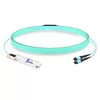
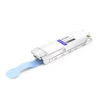
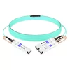
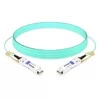
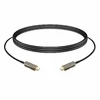
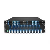
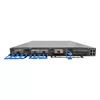
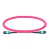
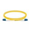
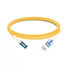
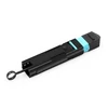
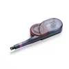
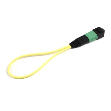
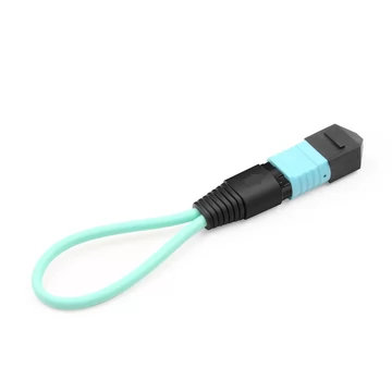
A fiber loopback cable is one of the fastest ways to check the basic operation of an optical transceiver or switch port and help isolate faults in a fiber network. It routes the transmitted optical signal back into the receiver, allowing technicians to verify the local optical path without requiring a second device at the far end. By comparing loopback results with normal link operation, engineers can narrow down whether a problem is associated with the transceiver, host port, or external cabling.
The catch is that a loopback only works correctly when it matches the connector type, fiber mode, optical interface, and transmit/receive mapping. For certain optical transceivers, the loopback must also provide sufficient attenuation to prevent receiver overload. Get any of these details wrong, and a quick diagnostic check can turn into hours of troubleshooting a fault that does not actually exist.
The Problem: A $5 Part Can Hold Up a $50,000 Test
A loopback plug is one of the least expensive items on a fiber test bench, yet an incorrectly selected or defective unit can invalidate a test result. When a transceiver fails a loopback test, engineers may initially suspect the optics. However, the problem could be the loopback itself: the wrong connector type, a multimode assembly used with single-mode optics, incompatible UPC and APC connector interfaces, an incorrect MPO fiber mapping, or excessive optical power reaching the receiver.
The consequences can be expensive. A mislabeled or mismatched loopback may lead to unnecessary RMA requests for functioning transceivers, waste hours of technician time, and delay deployments that would otherwise be ready to proceed. These risks can be reduced by selecting loopback assemblies from a supplier that provides clear specifications and application guidance.
Most loopbacks are sold as commodities: a part number and a price, with limited information about connector compatibility, insertion loss, durability, or fiber mapping. Buyers are often left to determine the critical details themselves. FiberMall treats loopback assemblies as precision connectivity components for optical testing, where reliable results depend on documented specifications, correct selection, and proper test procedures.
How to Choose the Right Fiber Loopback
Choosing a loopback comes down to four main decisions. Getting all four right helps ensure that the test setup is compatible with the optical interface and produces meaningful results.
- Connector type — LC connectors are widely used with SFP, SFP+, and SFP28 optical transceivers, as well as many duplex-fiber QSFP modules. SC connectors are common in certain telecom, access-network, and legacy applications. FC and MT-RJ connectors are used in specialized or older installations. MPO/MTP connectors support multi-fiber parallel optics, including 40G SR4, 100G SR4, 400G DR4, and 400G SR8. Match the loopback connector to the actual optical interface rather than relying on the transceiver form factor alone.
- Fiber mode — Single-mode fiber, typically OS2 (9/125 µm), is used with many long-reach and telecom optical transceivers. Multimode fiber, including OM1 (62.5/125 µm) and OM2/OM3/OM4 (50/125 µm), is used with compatible short-reach optical interfaces, particularly VCSEL-based optics. Selecting the wrong fiber mode can introduce unexpected coupling losses and produce unreliable test results. Always follow the transceiver's specified fiber requirements.
- Polish — UPC connectors are commonly used for standard physical-contact optical interfaces, while APC connectors feature an angled end face designed to reduce back reflections in applications such as CATV and PON networks. UPC and APC connectors should never be directly mated because their different end-face geometries can cause excessive loss, unreliable measurements, and connector damage. Match the polish type to the optical interface and mating connector.
- MPO/MTP polarity — Type A, B, and C describe different fiber-position mappings in MPO cable assemblies. A parallel-optics loopback must connect each transmit lane to its corresponding receive lane. The required mapping depends on the transceiver's lane arrangement and the connector's fiber count, as explained below.
Important: Connector and fiber compatibility alone do not guarantee a safe test. Before installing a short loopback, verify that the expected received optical power remains within the transceiver's specified operating range. Long-reach and high-output-power modules may require an attenuated loopback or an external optical attenuator.
Fiber Loopback Specifications & Performance Grades
A loopback's optical performance directly affects the quality and repeatability of test results. Insertion loss, return loss, connector durability, and operating conditions should all be considered when selecting an assembly.
FiberMall provides loopback solutions for different connector types and testing requirements. The following specifications describe representative performance targets for the relevant loopback configurations. Actual values should be confirmed against the selected product's datasheet, as performance can vary by connector, fiber type, polish, and construction.
Insertion Loss (UPC)
For LC/SC loopback assemblies with UPC connectors, insertion loss can be specified at ≤ 0.40 dB, with a typical target of ≤ 0.20 dB.
For standard MPO/MTP loopback assemblies, insertion loss can be specified at ≤ 0.75 dB, with a typical target of ≤ 0.35 dB. Low-loss MPO/MTP configurations may provide tighter insertion-loss limits.
These values are representative performance targets rather than universal limits for all loopback products.
Insertion Loss (APC)
For applicable LC/SC loopback assemblies with APC connectors, insertion loss can be specified at ≤ 0.60 dB, with a typical target of ≤ 0.30 dB.
APC MPO/MTP assemblies are also available for certain applications, but their insertion-loss specifications depend on the connector configuration and product design. They should not automatically be assigned the same values as UPC versions.
Return Loss (Single-Mode)
For single-mode LC/SC loopback assemblies, representative return-loss targets are ≥ 50 dB for UPC connectors and ≥ 60 dB for APC connectors.
Single-mode MPO/MTP loopback assemblies may be specified with return loss of ≥ 50 dB for suitable UPC configurations. APC MPO/MTP variants can provide higher return-loss performance, depending on the specific product.
Return loss measures the ratio of incident optical power to reflected optical power. Higher positive return-loss values indicate lower back reflection.
Return Loss (Multimode)
For multimode LC/SC and MPO/MTP loopback assemblies, a return-loss specification of ≥ 20 dB can serve as a baseline performance target.
Higher-performance connector assemblies may offer improved return-loss characteristics. Actual requirements should be based on the applicable product specification and testing environment.
Mating Cycles
Standard LC/SC loopback connectors are commonly designed for repeated use, with approximately 500 mating cycles serving as a representative durability target.
Standard MPO/MTP connector assemblies may also be rated for hundreds of mating cycles, depending on the connector design and manufacturer. Some configurations are specified for approximately 50 mating cycles, while more durable versions may support 500 or more.
Connector durability should be verified for each product rather than assumed to be identical across connector types or performance grades.
Operating Temperature
A representative operating temperature range for loopback assemblies is −10 °C to +70 °C.
The actual operating range depends on the materials, connector construction, and cable design. For use in industrial environments, select an assembly with a verified temperature rating appropriate for the application.
Fiber Types
LC/SC loopback assemblies can be manufactured using single-mode OS2 fiber or multimode OM1, OM2, OM3, and OM4 fiber.
MPO/MTP loopback assemblies are available with single-mode and multimode fibers, including OS2, OM3, and OM4, in various fiber-count configurations.
Common MPO/MTP configurations include 8, 12, 16, and 24 fibers, while higher fiber-count assemblies are available for specialized applications. The required fiber count must match the transceiver interface and its transmit/receive lane arrangement.
Applicable Standards
LC/SC loopback connector assemblies may reference standards such as TIA-568.3-D for optical fiber cabling, relevant IEC 61754 connector-interface standards, and Telcordia GR-326-CORE for applicable single-fiber optical connectors and cable assemblies.
MPO/MTP loopback assemblies may reference IEC 61754-7, TIA-604-5 (FOCIS 5), and TIA-568.3-D.
These standards cover different aspects of connector geometry, interoperability, and cabling systems. Compliance should be verified against the specific requirements and documented test results for each product.
Two Performance Grades, Clearly Specified
Most vendors offer limited information about loopback performance, making it difficult to distinguish standard assemblies from products designed for demanding test environments.
FiberMall can address these requirements through two performance categories, subject to the specifications and availability of the selected product:
- Standard Grade — Designed for general troubleshooting, occasional bench testing, and routine network commissioning. For suitable MPO/MTP configurations, a maximum insertion-loss target of ≤ 0.75 dB and connector durability of approximately 500 mating cycles provide a useful reference. Actual specifications depend on the connector type and selected model.
- Elite / Low-Loss Grade — Designed for repeated testing, production verification, and applications with tighter optical loss budgets. Suitable low-loss MPO/MTP configurations may target insertion loss of ≤ 0.35 dB and durability of ≥ 1,000 mating cycles when supported by the connector's verified specifications.
For accurate optical measurements, the insertion loss of the loopback and any additional test jumpers should be measured or accounted for in the test setup. A loopback should not be treated as a zero-loss connection.
There is no universal acceptable received-power range of 0 to −3 dBm. The correct receive-power range depends on the specific transceiver, its transmitter output, receiver sensitivity, and maximum permissible receiver input power.
For high-power or long-reach optical modules, an appropriately attenuated loopback may be necessary to protect the receiver and maintain valid test conditions. A basic loopback test can verify signal reception and, when supported by the host, link operation or error performance, but it does not independently establish receiver sensitivity or certify the complete fiber link.
MPO/MTP Polarity: Type A, B, or C?
Polarity is one of the biggest sources of confusion in multi-fiber loopback testing. MPO/MTP connectors can look identical externally while using different fiber-position mappings. An incorrect mapping may prevent a healthy transceiver from establishing a valid loopback connection.
The three common MPO cable polarity types are:
- Type A (straight-through) — Fiber positions are maintained from one connector to the other. For example, position 1 connects to position 1, position 2 connects to position 2, and so on. Type A assemblies are commonly used in structured cabling systems that implement Method A polarity management. The required transmit/receive crossover must be provided elsewhere in the channel when necessary.
- Type B (reversed) — Fiber positions are reversed from one end to the other. In a 12-fiber MPO assembly, position 1 connects to position 12, position 2 to position 11, position 3 to position 10, and so on. This reversed mapping is commonly used for direct parallel-optics connections and serves as the basis for many parallel-optics loopback configurations.
- Type C (pair-flipped) — Adjacent fiber pairs are crossed, such as position 1 to position 2, position 3 to position 4, and so on. Type C assemblies are primarily associated with certain duplex applications and structured-cabling systems. They are generally unsuitable as direct loopbacks for parallel optical interfaces that require transmit-to-receive mapping between separate fiber groups.
For 40G SR4, 100G SR4, and 100G DR4 transceivers using an MPO-12 interface, transmit lanes typically occupy fiber positions 1–4, while receive lanes occupy positions 9–12. A typical loopback mapping connects position 1 to 12, 2 to 11, 3 to 10, and 4 to 9, leaving positions 5–8 unused.
For 400G SR8 transceivers using a 16-fiber MPO interface, all eight transmit lanes must be routed to their corresponding eight receive lanes. The mapping therefore differs from the 8-fiber arrangement used by SR4 and DR4 modules.
As a rule of thumb, Type B-style reversed lane mapping is commonly used for SR4, DR4, and SR8 parallel-optics loopback applications, but the loopback must be designed for the correct fiber count and lane arrangement.
It is also important to distinguish a Type B MPO cable from a dedicated MPO loopback plug. A Type B cable defines the mapping between two connector ends, while a loopback plug must connect the appropriate transmit and receive positions within the local optical interface.
Connector gender and key orientation must also be checked. MPO connectors with guide pins must mate with compatible connectors without guide pins. Incompatible connector genders can prevent proper alignment or damage the interface.
Before ordering, confirm the transceiver's MPO interface, fiber count, pin configuration, and required lane mapping. The term "Type B" alone is not enough to specify every MPO loopback application.
Applications: Transceiver & Port Testing
FiberMall loopback cables are used in optical networking environments where transceivers and ports must be verified before deployment or during troubleshooting.
- Transceiver and port loopback verification — Check the basic functionality of the local optical transmit and receive paths, verify signal reception, and evaluate link or error status when supported by the host equipment. A basic loopback test does not independently measure receiver sensitivity.
- Network fault isolation — Connect a local transmitter back to its receiver to help determine whether a problem originates within the local device or elsewhere in the network. If the local loopback passes while the normal link fails, the external cabling, remote equipment, and configuration become the next areas to investigate.
- Manufacturing and burn-in testing — Support repeated operational checks during transceiver production, system integration, and equipment burn-in. Standard or low-loss loopback assemblies can be selected according to testing frequency, optical performance requirements, and connector durability.
- System commissioning — Verify individual switch or router ports before the network enters service. Multiple loopback assemblies can be used to support batch testing, provided the equipment supports the required diagnostic procedures.
- 40G/100G/400G parallel-optics testing — Use MPO/MTP loopback assemblies with the correct lane mapping to support multi-lane verification of compatible SR4, SR8, and DR4 transceivers. The connector's fiber count, polarity, and optical power requirements must match the transceiver specifications.
Loopback testing is a valuable part of network validation, but it should be combined with appropriate optical power measurements, bit-error-rate testing, and end-to-end link verification when a complete performance assessment is required.
Fiber Loopback Cable FAQ
What is a fiber loopback cable and how does it work?
A fiber loopback cable is a short optical assembly that connects a transceiver's transmit path back to its receive path, creating a local optical loop. This allows the host device or connected test equipment to verify signal reception and perform supported diagnostic tests without requiring a second network device.
Depending on the equipment, testing may include checking optical receive power, loss-of-signal status, link operation, or bit-error performance.
A successful loopback helps verify the local optical path but does not automatically certify the complete external fiber link. For long-reach optics, appropriate attenuation may be required to prevent receiver overload.
Which loopback do I need — LC, SC, or MPO/MTP?
Match the loopback connector to the optical interface of the transceiver or equipment being tested.
LC loopbacks are commonly used with SFP, SFP+, SFP28, and duplex-optics QSFP modules. SC loopbacks are used in certain telecom, access-network, and legacy systems. MPO/MTP loopbacks are required for compatible multi-fiber parallel optics, including 40G SR4, 100G SR4, 400G DR4, and 400G SR8.
FC and MT-RJ connectors are also used in selected telecom and legacy applications.
For MPO/MTP interfaces, verify the fiber count, connector gender, and transmit/receive lane mapping before selection.
What is the difference between single-mode and multimode loopback?
Single-mode loopbacks typically use OS2 (9/125 µm) fiber for compatible long-reach and telecom optical transceivers.
Multimode loopbacks use OM1 (62.5/125 µm) or OM2/OM3/OM4 (50/125 µm) fiber for compatible short-reach optical interfaces.
The loopback's fiber mode should match the optical transceiver's requirements. Using the wrong fiber type can introduce unexpected optical loss and produce misleading diagnostic results.
What MPO/MTP polarity do I need — Type A, B, or C?
Type B-style reversed fiber mapping is commonly used for direct parallel-optics applications such as 40G SR4, 100G SR4, 100G DR4, and 400G SR8.
However, a dedicated MPO/MTP loopback must connect each transmit lane to the correct receive lane according to the transceiver's actual interface configuration.
Type A is a straight-through cable mapping frequently used in certain structured-cabling systems, while Type C swaps adjacent fiber pairs and is mainly associated with duplex applications.
For example, an MPO-12 SR4 or DR4 loopback commonly connects fiber positions 1–12, 2–11, 3–10, and 4–9. An MPO-16 SR8 loopback requires a different mapping to accommodate eight transmit and eight receive lanes.
Confirm the fiber count, connector gender, and lane mapping against the transceiver datasheet, or ask FiberMall to help identify a compatible assembly.
What is the difference between UPC and APC polish?
UPC (Ultra Physical Contact) connectors use a polished physical-contact end face designed to minimize insertion loss and back reflection.
APC (Angled Physical Contact) connectors use an angled end face, typically 8°, to direct reflected light away from the optical path. They are commonly used in applications requiring high return-loss performance, such as CATV and PON networks.
UPC connectors are commonly blue for single-mode applications, while APC connectors are typically green. However, connector color alone should not replace verification of the actual specifications.
UPC and APC connectors should never be directly mated because their different end-face geometries can cause excessive insertion loss, poor return-loss performance, and potential connector damage.
Always select a loopback with the appropriate connector polish and verify compatibility with the mating optical interface.