FBT Optical Splitters: The Right Splitter for the Right Job
Every network engineer sourcing optical splitters faces the same dilemma: you need reliable passive components that remain within the project budget, supplied by a manufacturer whose products consistently meet their published specifications. Browse any fiber-optic marketplace, and you will find pages of manufacturers listing similar data-sheet values—but it is not always easy to determine which products can be trusted in a live network.
Why FBT? The Right Splitter for the Right Job
Not every optical distribution point needs a 1×64 PLC splitter. For many real-world deployments, FBT—or Fused Biconic Taper—technology is a practical and cost-effective engineering choice.
FBT splitters are manufactured by heating, fusing, and tapering optical fibers under controlled conditions. This process allows optical power to couple between the fibers, creating a passive device that divides or taps an incoming optical signal across multiple output ports.
PLC splitters are fabricated using planar silica waveguides and semiconductor-style lithography. They are generally preferred for high port counts, highly uniform output power, compact packaging, and broad wavelength coverage. FBT splitters, however, provide important advantages for low-port-count applications, especially when custom or unequal split ratios are required.
FBT is often the better choice when:
• You need a low port count, such as 1×2, 1×3, 1×4, or 1×8.
• You require an unequal split ratio, such as 90/10, 80/20, 95/5, or 99/1.
• Your system operates within specific wavelength windows, such as 1310 nm, 1490 nm, or 1550 nm.
• Cost is a significant consideration at a small optical distribution point.
• You need a nonstandard port count, such as 1×3, 1×7, or another custom configuration.
• You require a monitoring tap or custom coupler rather than a conventional equal-split PON splitter.
PLC is often the better choice when:
• You need a standard high-port-count splitter, such as 1×16, 1×32, or 1×64.
• You require highly uniform optical power across all output ports.
• You need broad and relatively flat performance across a wide wavelength range.
• You are designing a GPON, XGS-PON, NG-PON2, or coexistence network that may require support for multiple wavelength bands.
• You need a compact splitter for high-density fiber distribution.
• The product must meet defined environmental and reliability requirements for outdoor deployment.
Outdoor suitability should be determined from the actual product qualification, package design, temperature specifications, sealing, and enclosure—not from the FBT or PLC manufacturing method alone.
Commercial PLC splitters are most commonly supplied with equal split ratios and standard power-of-two port counts. Custom asymmetric and nonstandard-port-count PLC designs are technically possible, but they are less common and may require additional development cost and lead time. For low-port-count custom ratios, FBT is usually the more economical and readily available solution.
Even as PLC technology dominates high-density PON distribution, FBT splitters remain widely used in FTTH edge distribution, CATV networks, optical monitoring, selected mobile-transport applications, test and measurement systems, and specialty sensing. Their continued use is driven by flexible coupling ratios, low cost at small port counts, and the ability to support specialized wavelength requirements.
FBT Splitter Configurations: Find Your Exact Match
FiberMall offers a broad range of FBT splitters in multiple port counts, split ratios, fiber types, wavelength windows, and package formats. Each unit can be supplied with an individual optical test report covering the specified room-temperature performance parameters.
Available Configurations
The following insertion-loss values are typical reference limits for equal-split configurations. Actual values depend on the wavelength, connector type, package, fiber type, manufacturing tolerance, and product design.
For asymmetric FBT couplers, insertion loss is different at each output port and must be specified separately according to the required coupling ratio.
• 1×2: Typical maximum insertion loss of approximately 3.8 dB for a 50/50 splitter. Suitable for basic signal splitting, optical monitoring, and tap applications.
• 1×3: Typical maximum insertion loss of approximately 6.0 dB for an equal-split design. Suitable for custom three-way distribution.
• 1×4: Typical maximum insertion loss of approximately 7.1 dB. Suitable for small multi-dwelling units, rural FTTH distribution, and low-port-count optical networks.
• 1×8: Typical maximum insertion loss of approximately 10.5 dB. Suitable for low-port-count PON distribution, CATV nodes, and building distribution.
• 1×12: Typical maximum insertion loss of approximately 12.0 dB, depending on the cascaded design and uniformity requirements. Suitable for medium-sized building distribution.
• 1×16: Typical maximum insertion loss of approximately 14.0 dB. Suitable for larger distribution segments where an FBT design remains commercially or technically justified.
• 1×32: A 1×32 FBT splitter can be produced by cascading multiple coupler stages. However, it generally has higher accumulated loss, larger dimensions, greater port-to-port variation, and more temperature-dependent performance than a monolithic PLC splitter. PLC is normally preferred for standard 1×32 PON deployments.
All figures should be confirmed against the data sheet for the exact product configuration.
Split Ratios—Standard and Custom
One of the primary advantages of FBT technology is its ability to support both equal and unequal split ratios economically at low port counts.
Custom ratios can often be specified in increments of approximately 1%, subject to manufacturing feasibility, wavelength, port count, and tolerance requirements.
Common 1×2 coupling ratios include:
• 50/50
• 45/55
• 40/60
• 35/65
• 30/70
• 25/75
• 20/80
• 15/85
• 10/90
• 5/95
• 3/97
• 2/98
• 1/99
For an asymmetric coupler, each output has a different theoretical splitting loss. For example, an ideal 90/10 coupler has approximately 0.46 dB of theoretical splitting loss on the 90% path and approximately 10.46 dB on the 10% path, before excess loss, connector loss, and manufacturing tolerance are added.
For this reason, unequal-ratio products should be specified with separate insertion-loss limits for the main and tap ports.
Wavelength Options
FBT splitters and couplers can be manufactured for different optical windows.
• Single-window products: Commonly optimized for 1310 nm, 1490 nm, or 1550 nm.
• Dual-window products: Commonly optimized for 1310/1550 nm.
• Triple-window products: Commonly specified for 1310/1490/1550 nm.
• Specialty-wavelength products: May be designed for wavelengths such as 460 nm, 532 nm, 630 nm, 780 nm, or 980 nm for sensing, biomedical, laser, laboratory, and other specialized applications.
The stated center wavelengths alone do not define the complete operating range. For PON applications, verify that the splitter meets the required insertion loss, uniformity, PDL, and return-loss specifications across the full upstream and downstream wavelength bands used by the system.
Technical Specifications: Numbers That Translate to Network Performance
Every data sheet lists similar parameters. What matters is understanding how those parameters affect signal integrity, optical margin, and long-term reliability.
Insertion Loss
For a 50/50 1×2 FBT splitter, a typical insertion-loss target may be approximately 3.8 dB, with a maximum value of approximately 4.0 dB.
The theoretical splitting loss of a perfect 50/50 splitter is approximately 3.01 dB. The difference between the theoretical value and the actual insertion loss results from excess loss, fiber coupling loss, splices, connectors, and manufacturing tolerances.
For an equal-split 1×8 FBT splitter, a typical insertion-loss value may be approximately 10.2 dB, with a maximum value of approximately 10.5 dB.
Insertion loss must always be included in the optical link-budget calculation. In cascaded designs, the loss of each stage, connector, splice, and patching point must be added.
Return Loss
Return loss indicates how effectively the component limits reflected optical power.
A common connectorized product specification may require:
• At least 50 dB return loss for UPC connections.
• At least 55 dB, and often 60 dB or higher, for APC connections.
The exact value depends on the connector type, polishing quality, product design, and test method. APC connectors normally provide better reflection performance than UPC connectors.
High return loss helps reduce unwanted back-reflections that can affect transmitters, analog optical systems, and sensitive measurement equipment.
Directivity
A typical directivity target is at least 55 dB.
High directivity minimizes unwanted optical coupling between output ports. This is especially important in monitoring, sensing, analog, and bidirectional optical applications.
Polarization-Dependent Loss
A typical PDL target may be no more than 0.15 dB per coupler stage.
Low PDL helps maintain stable optical performance as the polarization state changes in the fiber. In a cascaded splitter, PDL and other variations can accumulate across multiple stages.
Uniformity
For an equal-split 1×8 FBT device, a typical uniformity target may be no more than 1.0 dB.
Uniformity describes the difference between the highest-loss and lowest-loss output ports. Lower uniformity values reduce output-power variation between subscribers or downstream devices.
Uniformity is primarily relevant to equal-split products. It should not be applied in the same way to intentionally asymmetric couplers.
Operating Temperature
Qualified products may be specified for operation from -40 °C to +85 °C.
This temperature range alone does not mean that the component can be installed outdoors without protection. The splitter must still be installed in a suitable weather-sealed enclosure, cabinet, closure, or rack system.
For cascaded FBT designs, temperature-dependent loss can accumulate across multiple coupler stages. Environmental performance should therefore be confirmed for the complete assembled splitter, not only for an individual coupler element.
Fiber Type
Common options include:
• SMF-28e+ or other G.652.D-compliant single-mode fiber.
• G.657.A bend-insensitive single-mode fiber.
The selected fiber should match the installed fiber plant, bend-radius requirements, splice process, and package design.
FBT vs. PLC Splitter: A Decision Guide for Engineers
How They Compare
Manufacturing technology
FBT splitters are produced by heating, fusing, and tapering optical fibers to create controlled optical coupling.
PLC splitters use a planar lightwave circuit, normally consisting of silica waveguides fabricated on a chip.
Practical split count
FBT is most practical for low port counts, particularly 1×2 through 1×8. Configurations up to 1×16 are common in some applications, while 1×32 can be produced through cascading but usually involves higher accumulated loss, larger dimensions, and greater variation.
PLC is generally preferred for standard high-port-count configurations such as 1×16, 1×32, and 1×64. Some manufacturers also offer 1×128 products.
Split-ratio flexibility
FBT provides high flexibility for low-port-count equal and unequal ratios. Custom tap ratios such as 90/10, 95/5, and 99/1 are widely available.
Commercial PLC products are most commonly supplied as equal-split devices with standard port counts. Asymmetric and nonstandard PLC designs are technically possible, but they are less common and may require custom development.
Wavelength range
FBT splitters are generally optimized for one or more defined wavelength windows. Their coupling ratio and insertion loss may change as the operating wavelength moves away from the design range.
Telecom-grade PLC splitters generally provide broader and flatter wavelength performance. Many products are specified across a wide range such as 1260–1650 nm, but the exact range must be confirmed from the product data sheet.
Cost at low port counts
At 1×2, 1×3, 1×4, and often 1×8, FBT is usually less expensive, particularly for custom ratios or nonstandard configurations.
PLC may be more expensive for small custom designs because of chip fabrication and packaging requirements.
Cost at higher port counts
At 1×16 and above, cascaded FBT designs become more complex and may require more components, splices, and packaging space.
PLC is usually more economical and consistent for standard high-port-count equal-split products.
Temperature and wavelength stability
FBT products can provide good performance within their specified operating windows. However, wavelength-dependent coupling and temperature effects may become more significant in cascaded designs.
PLC products generally provide flatter spectral response and more consistent multiport uniformity. Environmental performance still depends on the specific design, packaging, and qualification standard.
Physical size
Low-port-count FBT couplers can be extremely compact.
High-port-count FBT splitters become larger because they are constructed by cascading multiple coupler stages.
PLC splitters are compact at high port counts because the complete splitting structure is integrated onto a single chip.
XGS-PON and NG-PON2 suitability
Conventional narrowband FBT splitters should not automatically be considered suitable for XGS-PON, NG-PON2, or coexistence networks.
They should be used only when the exact product is explicitly specified and tested across all required upstream, downstream, video-overlay, and coexistence wavelength bands.
Broadband PLC splitters are generally preferred for current and future multiwavelength PON systems because of their flatter spectral response.
Custom port counts
FBT splitters can be configured with nonstandard port counts such as 1×3, 1×7, or 1×11 through customized cascaded designs.
Custom nonstandard PLC port counts are technically possible but are less commonly stocked and may require custom chip design or fabrication.
Custom lead time
Low-port-count custom FBT ratios can often be produced within approximately 3–7 business days, depending on materials, connectorization, testing, order quantity, and production capacity.
Custom PLC products may require several weeks, particularly if a new chip design or fabrication run is required. All lead times should be confirmed at the time of quotation.
The Engineering Decision Tree
Choose FBT if:
• Your split count is 1×8 or below and cost is a significant constraint.
• You need an unequal tap ratio such as 90/10, 95/5, or 99/1 for monitoring or optical-power management.
• You are building a CATV or analog optical distribution node within a defined wavelength window.
• You need a nonstandard port count that is not readily available as a standard PLC product.
• You are prototyping, performing laboratory tests, or need quick-turn custom ratios.
• You require a specialty-wavelength coupler for sensing, biomedical, laser, or research applications.
Choose PLC if:
• You are deploying standard 1×16, 1×32, or 1×64 equal-split PON distribution.
• Your network must support XGS-PON, NG-PON2, coexistence, or future wavelength upgrades.
• You require broad and relatively wavelength-independent performance.
• Uniformity across all output ports is critical.
• You need the smallest practical footprint for high-density fiber management.
• You need a product specifically qualified for defined outdoor, temperature, humidity, mechanical, and reliability requirements.
Packaging and Connector Options
FBT splitters are available in multiple package formats to match different installation environments.
Steel Tube—Bare Fiber
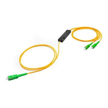
A typical 1×2 steel-tube package measures approximately 3 mm × 54 mm and provides a compact inline form factor.
It is best suited to:
• Splicing into fiber splice trays.
• Embedding inside larger optical assemblies.
• Integrating into closures or modules.
• Field pigtailing and custom equipment manufacturing.
Common fiber options include:
• 250 μm bare fiber.
• 900 μm loose-tube or buffered fiber.
• Standard lead lengths of approximately 1.0 m, with custom lengths available.
ABS Box
Common dimensions include approximately 100 mm × 80 mm × 10 mm or a smaller format such as 89 mm × 19 mm × 10 mm.
ABS-box splitters are suited to:
• Surface-mounted installations.
• Patch-panel integration.
• Structured cabling.
• Indoor equipment rooms.
• Installation inside protected cabinets or enclosures.
Available features may include:
• Strain-relief boots.
• Labeled input and output fibers.
• Mounting holes.
• Connectorized pigtails.
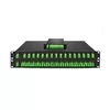
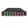
LGX Cassette and Rack-Mount Packaging
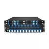
A common LGX format is approximately 129 mm × 103 mm × 29 mm. Rack-mounted products may be supplied in a standard 1U, 19-inch chassis.
These formats are best suited to:
• Data center fiber distribution frames.
• CATV headend racks.
• Optical distribution frames.
• Telecom equipment rooms.
• High-density connectorized installations.
Typical features include:
• Front-facing adapter ports.
• Internal splice management.
• Cable-management structures.
• Clearly identified input and output ports.
Connector Options
Available connector options may include:
• SC/UPC
• SC/APC
• LC/UPC
• LC/APC
• FC/UPC
• FC/APC
• ST/UPC
• E2000/APC
Different connector types can be specified on the common and output ports when required. For example, an SC/APC common port may be combined with LC/UPC output ports.
When mixing connector types, verify adapter compatibility, return-loss requirements, end-face type, and the reflection sensitivity of the application.
Applications: Where FBT Splitters Perform
FTTH and FTTx Edge Distribution
FBT’s cost advantage at low port counts makes it suitable for the final distribution point before the subscriber.
Typical examples include:
• Small multi-dwelling-unit splits.
• Rural drop points.
• Low-port-count edge distribution.
• Situations where installing a 1×32 PLC splitter would leave many ports unused.
For PON use, the FBT splitter must cover the complete required upstream and downstream wavelength bands—not only the nominal center wavelengths.
CATV and RF Overlay Networks
FBT splitters are widely used in CATV and analog optical distribution systems operating in specified wavelength windows such as 1310 nm or 1550 nm.
Custom split ratios allow engineers to balance optical power across branches, nodes, receivers, and cascaded amplifier stages.
Because CATV and analog optical systems can be sensitive to reflections and optical-power variation, insertion loss, return loss, directivity, and connector type must be carefully controlled.
PON Network Monitoring and Troubleshooting
A 90/10 or 95/5 FBT tap coupler can divert a small portion of optical power to monitoring equipment while allowing most of the signal to continue through the live path.
This allows passive monitoring without physically interrupting the fiber connection, provided that:
• The added insertion loss is included in the optical link budget.
• The remaining power is sufficient for the OLT and ONT receivers.
• The monitoring equipment supports the relevant upstream and downstream wavelengths.
• Burst-mode upstream PON signals are measured with suitable equipment.
• Connector reflections and cleanliness are controlled.
A tap coupler does not eliminate its effect on the optical path; it introduces measurable loss that must be engineered into the system.
Selected 5G Fronthaul and Backhaul Applications
FBT couplers may be used in selected PON-based mobile-transport, optical-monitoring, sensing, or low-port-count passive distribution applications.
However, many 5G fronthaul and backhaul systems use point-to-point Ethernet, WDM, or active transport equipment rather than passive power splitting.
The suitability of an FBT splitter therefore depends on the specific architecture, optical protocol, wavelength plan, power budget, and redundancy requirements.
Test and Measurement Laboratories
R&D teams and production test environments use FBT splitters and couplers because they can be ordered with:
• Custom coupling ratios.
• Nonstandard port counts.
• Defined wavelength windows.
• Shorter custom lead times.
• Monitoring-tap configurations.
These capabilities allow test engineers to order the exact optical distribution or tap ratio required rather than using the nearest standard equal-split device.
Industrial and Specialty Fiber Sensing
At specialty wavelengths such as 460–980 nm, FBT splitters may support:
• Biomedical imaging.
• Structural monitoring.
• Industrial sensing.
• LiDAR signal distribution.
• Laser systems.
• Laboratory experiments.
• Quantum-optics research.
Standard telecom PLC splitter products may not be readily available or economical at these wavelengths. The fiber type, coating, numerical aperture, power handling, and connector materials must be selected for the actual wavelength and application.
Frequently Asked Questions
What is the difference between an FBT splitter and a PLC splitter?
FBT splitters are manufactured by heating, fusing, and tapering optical fibers to create controlled optical coupling.
PLC splitters use planar silica waveguides fabricated on a chip through semiconductor-style processing.
FBT generally provides the greatest cost and customization advantages at low port counts, particularly from 1×2 to 1×8 and for unequal split ratios.
PLC is generally preferred for high port counts, highly uniform equal splits, compact packaging, and broad wavelength coverage.
Commercial PLC splitters are usually supplied in standard equal-split configurations, although custom asymmetric PLC devices are technically possible.
Which split ratio should I choose for my network?
For equal distribution, use a 50/50 ratio for a 1×2 splitter or the equivalent equal-power distribution for a higher-port-count design.
For monitoring, a 90/10 or 95/5 tap ratio sends most of the optical power through the main path while diverting a smaller portion to the monitoring equipment.
The best ratio depends on:
• Available transmitter power.
• Receiver sensitivity.
• Existing fiber and connector loss.
• Required monitoring-equipment input power.
• Safety margin.
• Wavelength.
• Number of cascaded components.
The split ratio should be selected using a complete optical link-budget calculation.
Are FBT splitters compatible with GPON and EPON networks?
FBT splitters can be used in GPON or EPON networks when their specified operating bands cover the complete upstream and downstream wavelength ranges required by the system.
For GPON, this generally means verifying performance across the applicable upstream and downstream bands, rather than checking only individual center wavelengths such as 1310 nm and 1490 nm.
A triple-window product may also support a 1550 nm RF-video overlay, but the exact band coverage must be confirmed.
Insertion loss, uniformity, PDL, return loss, directivity, and temperature stability must also meet the system link-budget requirements.
For XGS-PON, NG-PON2, or coexistence networks, conventional narrowband FBT products are generally not recommended unless they are explicitly designed and qualified across all required wavelength bands. Broadband PLC splitters are normally preferred.
What does insertion loss mean for my network?
Insertion loss is the amount of optical power lost as the signal passes through the splitter or coupler.
In a 50/50 1×2 splitter, each output ideally receives half of the input optical power. This corresponds to a theoretical splitting loss of approximately 3.01 dB.
Actual insertion loss is higher because of:
• Excess loss in the coupler.
• Splices.
• Connectors.
• Fiber attenuation.
• Manufacturing tolerances.
• Package and routing losses.
A device with a maximum insertion loss of 3.8 dB leaves less optical power available at each output than an ideal lossless 50/50 splitter.
For an asymmetric splitter, the insertion loss is different at each output. A 90/10 splitter, for example, cannot be described by a single insertion-loss value for both ports.
All splitter losses must be included in the link budget to ensure that sufficient power reaches each ONT, receiver, amplifier, or monitoring device.
How reliable are FBT splitters for outdoor deployment?
FBT splitters rated for operation from -40 °C to +85 °C can be used in outdoor systems when they are installed in an appropriate protected enclosure.
Key considerations include:
• Install the splitter inside a weather-sealed closure, cabinet, pedestal, or other suitable enclosure.
• Confirm the humidity, condensation, vibration, shock, and mechanical requirements.
• Verify the package, cable, connector, and strain-relief design.
• For cascaded designs above 1×8, account for accumulated temperature-dependent loss and port variation.
• Review environmental qualification data for the complete product.
Per-unit optical testing is normally performed at specified room-temperature conditions. Full-temperature performance may be verified through product qualification, representative sampling, or environmental testing unless the purchase specification requires every unit to be tested across the complete temperature range.
Can I order a custom split ratio that is not listed on a standard data sheet?
Yes. Custom split ratios are one of the main advantages of FBT technology.
Ratios can often be specified in increments of approximately 1%, subject to:
• Wavelength.
• Fiber type.
• Port count.
• Required tolerance.
• Package.
• Connectorization.
• Order quantity.
• Manufacturing feasibility.
The engineering team should confirm the required ratio, tolerance, insertion-loss limits for each output, and wavelength range before production.
A serial-numbered test report can be supplied to verify the actual achieved coupling ratio and insertion loss.
Typical custom lead time may be approximately 3–7 business days, subject to production capacity and final configuration.
What connector types are available, and can I mix connectors on one splitter?
Available options may include SC/UPC, SC/APC, LC/UPC, LC/APC, FC/UPC, FC/APC, ST/UPC, and E2000/APC.
The common input port can use one connector type while the output ports use another. For example, an SC/APC connector may be used on the common port while LC/UPC connectors are used on the output ports for high-density patching.
When specifying mixed connectors, confirm:
• The correct mating adapter at each location.
• UPC versus APC end-face compatibility.
• Return-loss requirements.
• Fiber type.
• Connector keying and polarity.
• Patch-panel density.
UPC and APC connectors must never be directly mated to each other.
How are FBT splitters tested before shipping?
A complete optical test may include:
• Insertion loss at each output port using a calibrated light source and optical power meter.
• Split-ratio or coupling-ratio verification.
• Return loss using an appropriate optical return-loss test method.
• Polarization-dependent loss.
• Directivity.
• Port-to-port uniformity for equal-split products.
• Visual inspection and connector end-face inspection.
Results can be recorded on a serial-numbered test sheet for warranty, traceability, and incoming-quality verification.
Routine per-unit tests are normally performed at specified laboratory conditions. Environmental and full-temperature performance should be supported by qualification data or performed separately when required by the customer specification.
Do you offer volume discounts for large deployments?
Volume pricing may be available for orders of 100, 500, 1,000, or more units, depending on the configuration, connector type, package, testing requirements, and delivery schedule.
Net 30 or Net 60 payment terms may be available to qualified business accounts, subject to credit review and approval.
Contact the sales team with the required configuration, projected quantities, delivery schedule, and annual demand for a tailored quotation.
What is the difference between steel-tube and ABS-box packaging?
Steel-tube packaging is the most compact option. A typical 1×2 device may use a package measuring approximately 3 mm × 54 mm.
Bare or buffered fiber leads exit directly from the metal tube. This format is intended to be:
• Spliced into a fiber tray.
• Integrated into a larger assembly.
• Installed inside a protected enclosure.
• Used where minimum size is important.
ABS-box packaging provides a larger protective plastic housing with strain relief, routing space, mounting features, and optional connectorized pigtails.
A typical ABS package may measure approximately 100 mm × 80 mm × 10 mm, although smaller formats are also available.
Choose a steel-tube package when the splitter will be fusion-spliced or integrated into another product. Choose an ABS-box package when additional mechanical protection, mounting, labeling, or connectorized installation is required.