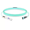
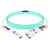
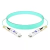
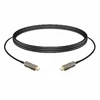
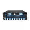
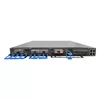
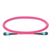
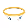
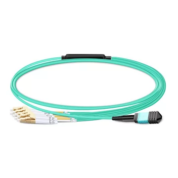
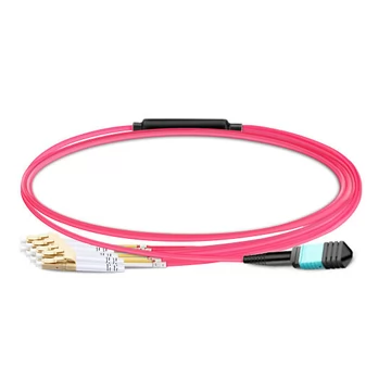
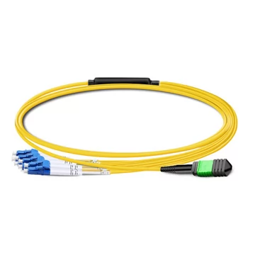
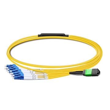
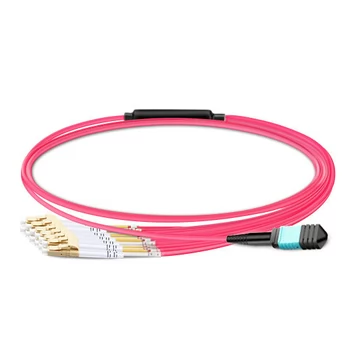
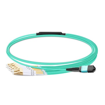
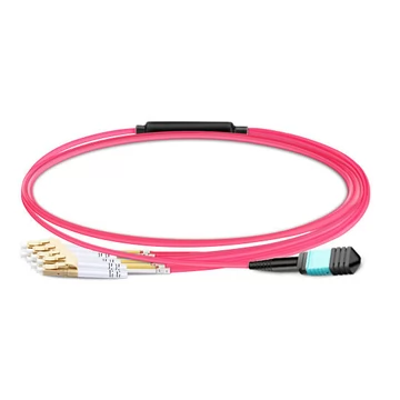
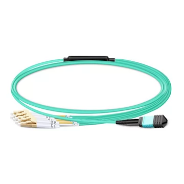
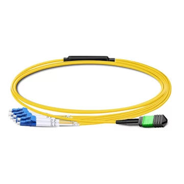
An MPO-to-LC breakout cable fans a single multi-fiber MPO connector out into multiple duplex LC pairs, converting a high-speed 40G, 100G, or 400G port into four to eight lower-speed links. It provides an efficient, direct path to link high-density QSFP/QSFP-DD switch ports to individual SFP interfaces, patch panels, or servers without adding adapter cassettes. Correct fiber count, polarity method, and transceiver breakout capabilities are essential to ensure the link comes up successfully during commissioning.
What Is an MPO-to-LC Breakout Cable?
An MPO-to-LC breakout cable—also known as an MPO-LC fanout cable or harness cable—features an MPO/MTP connector on one end and multiple duplex LC connectors on the other. While some vendor terminology refers to MPO-to-MPO conversion assemblies as breakout cables, in this context "breakout" specifically designates an MPO interface transitioning to multiple discrete LC pairs.
It serves a distinct purpose from an MPO trunk cable, which carries MPO connectors on both ends for backbone and horizontal cross-connects. A breakout cable operates primarily at the access or aggregation layer of the network, where a single high-bandwidth port connects directly to multiple downstream devices.
Applications: Breaking Out One Port into Many
Breakout cables are purely passive optical assemblies: they route a transceiver's optical lanes directly into independent channels without active electronics. The cable pinout must align with the transceiver's lane allocations:
· 40G to 4× 10G: Employs a QSFP+ SR4 transceiver paired with an MPO-12 (or MPO-8) to 4× LC duplex breakout cable.
· 100G to 4× 25G (Multimode): Employs a QSFP28 SR4 transceiver paired with an MPO-12 (or MPO-8) to 4× LC duplex breakout cable.
· 100G to 4× 25G (Single-mode): Employs a QSFP28 PSM4 transceiver paired with an MPO-12 single-mode (OS2) to 4× LC duplex breakout cable. (Note: Standard 100G DR modules operate as a single 1-lane 100G PAM4 interface over duplex LC; breaking out 100G to 4× 25G NRZ over single-mode requires a 4-lane parallel optic like PSM4.)
· 400G to 8× 50G: Employs a QSFP-DD SR8 or OSFP SR8 transceiver paired with an MPO-16 to 8× LC duplex breakout cable.
· 400G to 4× 100G: Employs a QSFP-DD DR4 or XDR4 transceiver paired with an MPO-12 (APC) single-mode to 4× LC duplex breakout cable.
These configurations support spine-and-leaf network architectures, top-of-rack (ToR) server aggregation, storage area networks (SANs), and high-throughput AI/GPU cluster interconnects.
Polarity: Type A, Type B, and Type C
Optical polarity defines the continuous transmit (Tx) to receive (Rx) path across an entire link, making it the most frequent cause of link failure when misconfigured. The TIA-568 standard defines three primary MPO polarity methods:
· Type A (Straight-Through): Uses a Key-Up to Key-Down orientation. The optical fibers map sequentially pin-for-pin (Pin 1 to Pin 1, Pin 2 to Pin 2, through Pin 12 to Pin 12).
· Type B (Reversed): Uses a Key-Up to Key-Up orientation. The optical fibers map in reverse order (Pin 1 to Pin 12, Pin 2 to Pin 11, through Pin 12 to Pin 1).
· Type C (Pair-Flipped): Uses a Key-Up to Key-Down orientation. Adjacent fiber pairs are transposed (Pin 1 to Pin 2, Pin 2 to Pin 1, Pin 3 to Pin 4, and so on).
In a breakout harness, polarity determines how the Tx and Rx lanes are presented across each duplex LC connector. Method B (Type B) is the standard in parallel-optic enterprise and hyperscale data centers because it ensures correct Tx-to-Rx orientation across symmetric channel architectures. Polarity must be implemented consistently end-to-end; inserting a Type A breakout assembly into a Method B link breaks the signal path.
Choosing Fiber Count and Optical Fiber Mode
Selecting the correct cable geometry requires matching the physical fiber count and core type to the transceivers:
Fiber Count Options:
· 8-Fiber (MPO-8): Terminates to 4× LC duplex pairs. Designed specifically for QSFP+/QSFP28 4-lane parallel optics, leaving no unused dark fibers.
· 12-Fiber (MPO-12): Terminates to 4× LC duplex pairs (leaving the inner 4 fibers unpopulated) for standard 40G/100G SR4 optics, or to a full 6× LC duplex pairs for high-density patch-panel distribution.
· 16-Fiber (MPO-16): Terminates to 8× LC duplex pairs. Specifically required for 400G SR8 (QSFP-DD / OSFP) multimode interfaces.
· 24-Fiber (MPO-24): Terminates to 12× LC duplex pairs, providing high-density breakout across multi-port modular cassettes.
Fiber Types:
· OM3 Multimode: Supports reaches up to 100 meters on standard 40G/100G SR4 links.
· OM4 Multimode: Extends reach up to 150 meters on 40G/100G links and provides optical margin for high-speed multi-gigabit connections.
· OM5 Multimode: Wideband multimode fiber (WBMMF) optimized for Short Wavelength Division Multiplexing (SWDM) and future multi-wavelength applications.
· OS2 Single-Mode: Optimized for long-reach intra-campus runs, 400G DR4/XDR4, and parallel single-mode (PSM4) breakouts requiring angled physical contact (APC) ferrules on the MPO connector.
Breakout-Mode Compatibility: The Vital Requirement
Because breakout cables are passive assemblies, channel channelization depends entirely on whether both the switch operating system (NOS) and the optical transceiver support lane breakout:
· 40G QSFP+ SR4 / CSR4: Breakout-capable switches map the port to 4× 10G links using an MPO-12 (or MPO-8) to 4× LC duplex assembly. (Confirm transceiver support; standard base-line enterprise optics often do not support channel splitting.)
· 100G QSFP28 SR4: Splits into 4× 25G links using an MPO-12 (or MPO-8) to 4× LC duplex multimode assembly.
· 100G QSFP28 PSM4: Splits into 4× 25G links using an MPO-12 to 4× LC duplex single-mode assembly.
· 400G QSFP-DD SR8: Splits into 8× 50G PAM4 links using an MPO-16 to 8× LC duplex multimode assembly.
· 400G QSFP-DD DR4: Splits into 4× 100G PAM4 links using an MPO-12 (APC) to 4× LC duplex single-mode assembly.
Build Characteristics and Specifications
Precision MPO Terminations
Optical stability depends on tight ferrule dimensional tolerances. Using precision connectors (such as SENKO components) ensures exact fiber pitch, proper spring tension, and repeatable core alignment across all pins, maintaining low loss even over frequent mating cycles.
Graded Insertion Loss
Channel link budgets dictate the required insertion loss (IL) grade:
· Standard Loss (IL ≤ 0.7 dB): Recommended for direct short-distance interconnects with minimal intermediate connection points.
· Low Loss (IL ≤ 0.35 dB): Essential for multi-hop enterprise patching, longer runs, and PAM4 links where total attenuation margins are constrained.
LSZH Outer Jackets
Low-smoke zero-halogen (LSZH) outer jackets meet fire and safety standards within modern data halls by reducing toxic and corrosive gas emissions during combustion. Assemblies are standardly available in lengths ranging from 1 meter to 50 meters (including 1m, 3m, 5m, 7m, 10m, 15m, 20m, 30m, and 50m), as well as custom-engineered lengths for specialized cable pathways.
Frequently Asked Questions
What is the difference between an MPO breakout cable, a harness, and a trunk cable?
An MPO-to-LC breakout cable (also termed a fanout or harness) features a multi-fiber MPO connector on one end that splits into discrete duplex LC connectors on the opposite end. A trunk cable has MPO connectors on both ends and functions as a high-density structured backbone run. "Breakout" and "harness" describe point-to-multipoint topologies, while "trunk" describes point-to-point trunking.
What polarity type should I select for an MPO-to-LC breakout cable?
For the vast majority of modern parallel-optic data center architectures, Method B (Type B, Key-Up to Key-Up) is standard because it preserves lane-to-lane duplex transmit/receive orientation across symmetric patching. Verify your structured cabling design beforehand, as combining disparate polarity standards disrupts communication.
Should I choose an 8-fiber or 12-fiber MPO for a 40G/100G SR4 breakout?
Because 40GBASE-SR4 and 100GBASE-SR4 optics utilize 4 lanes (8 active fibers: 4 transmit, 4 receive), both 8-fiber and 12-fiber cables are functionally compatible. In 12-fiber assemblies, the 4 center fibers remain dark, whereas 8-fiber cables eliminate unused glass. An MPO-16 interface is reserved for 8-lane configurations, such as 400G SR8.
Can any 40G or 100G port break out into 4× 10G or 4× 25G links with a passive cable?
Only if the network switch port and the transceiver module firmware support breakout/channelization mode. A passive optical cable simply maps the physical fibers; it cannot perform signal conversion or protocol negotiation.
How do I determine if my transceiver supports port breakout?
Review the hardware datasheet and switch OS configuration guide. For single-mode 100G-to-4×25G, a parallel transceiver (such as PSM4) is required rather than a duplex optic. If you are unsure, provide your equipment model numbers to your cabling provider to confirm transceiver and cable interoperability.
What insertion loss specification should I select?
Base your selection on the overall optical power budget. Standard insertion loss (≤0.7 dB) is suitable for point-to-point links with minimal mating interfaces. Low-loss variants (≤0.35 dB) are strongly recommended for structured cross-connect architectures or high-order modulation schemes (such as 50G/100G PAM4) where link margins are tighter.