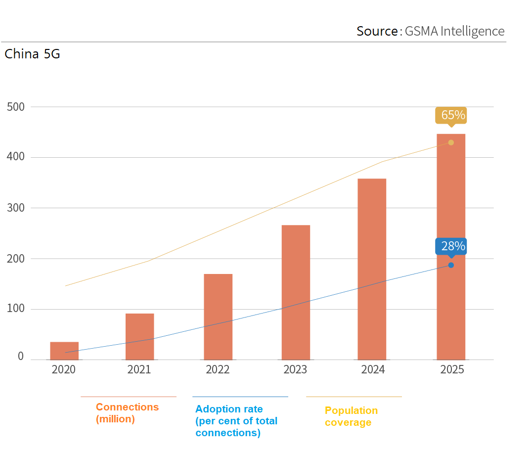
5G was launched in 2019 and has seen rapid growth in Asia, North America, and Europe. The GSMA predicts that 5G connections will continue to grow over the next five years and the connections will reach 500 million by 2025.
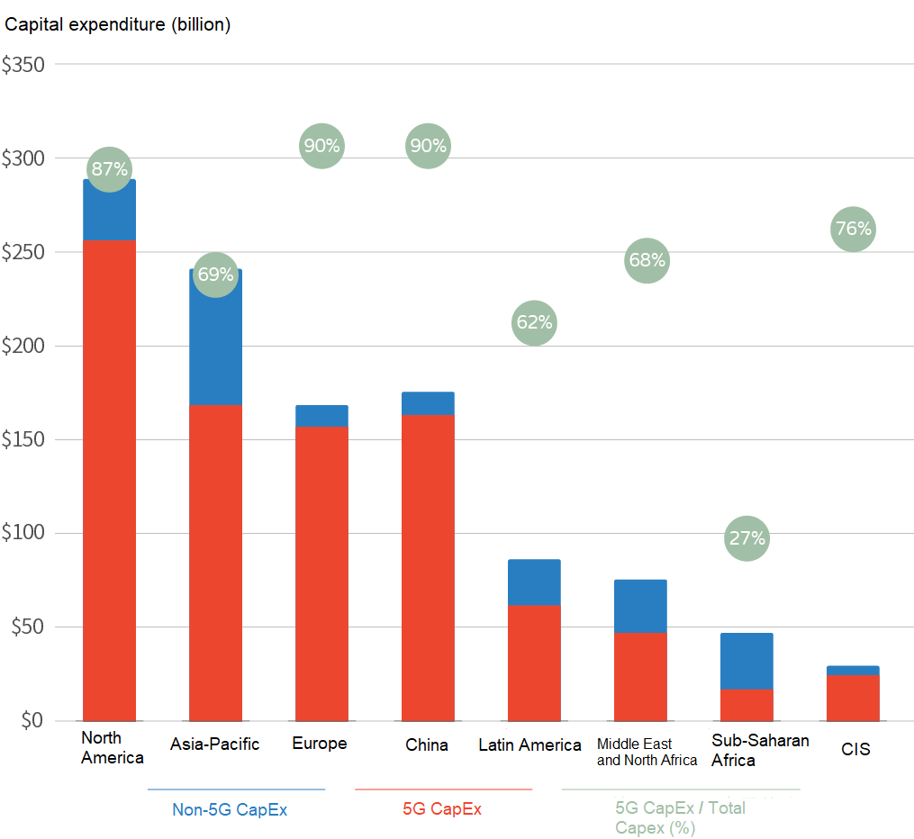
Global operators will invest about $1.1 trillion in mobile communications between 2020 and 2025, of which about 80% will be spent on 5G capital expenditures.
Figure 1-2 Capital expenditures in mobile communications
2. 5G wireless front-haul interface requires a minimum rate of 25Gbit/s
5G wireless communication requires more spectrum resources than 4G for enhanced mobile broadband (eMBB), ultra-reliable and low-latency communication (URLLC), and massive Internet of things (mIoT).
5G uses a spectrum lower than 6GHz FR1 currently, which supports a maximum bandwidth of 100Mbit/s, five times that of 4G LTE. The Common Public Radio Interface (CPRI) protocol requires at least 100Gbit/s of fronthaul channels when there are 64 channels and a bandwidth of 100MHz. However, in 2017, the industry is not ready for 100Gbit/s optical modules. Therefore, the Enhanced CPRI (eCPRI) protocol was developed.
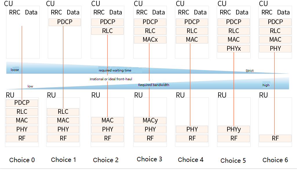
Figure 2-1 Different split modes of eCPRI
The eCPRI protocol defines multiple split modes. Interfaces at higher protocol layers require lower transmission bandwidth. In the mainstream split scheme, some physical-layer signal-processing functions are transmitted from the baseband to the antenna side, and only the 25Gbit/s rate needs to be obtained from the fronthaul interface. In recent years, the demand for mainstream front-haul optical modules has evolved from 10Gbit/s in the 4G era to 25Gbit/s in the 5G era.
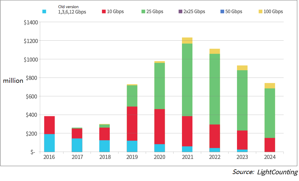
Considering that the low- and mid-range bands in the wireless spectrum are already crowded, 3GPP has allocated higher frequency bands for 5G. However, this results in higher signal loss. Therefore, the density of 5G base stations is higher than that of 4G, and the requirements for optical modules are higher to ensure good communication quality. LightCounting predicts that 25G optical modules for 5G fronthaul will exceed 50% of all the optical modules sold in the next five years.
Figure 2-2 Sales of wireless front-haul optical modules
25G optical modules are mainly used for wireless front-haul. Therefore, reusing existing resources in the 25GE Ethernet industry can help telecom operators significantly reduce costs and increase the efficiency of optical solutions.
3. Typical 5G wireless fronthaul scenario
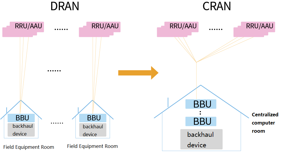
Typical architectures for wireless fronthaul are Distributed RAN (DRAN) or Centralized RAN (CRAN). In CRAN mode, the BBU is located in the central office. This significantly reduces the space and power consumption of ancillary equipment (especially air conditioners), resulting in lower CAPEX and OPEX. In addition, CBBU constitutes a BBU baseband pool, which can be centrally managed and scheduled for different network needs.
Figure 3-1 DRAN and CRAN front-haul systems
Due to the addition of base stations, 5G network construction is much more expensive than 4G, and acquiring sites is challenging. Therefore, CRAN is the first choice for large-scale deployment.
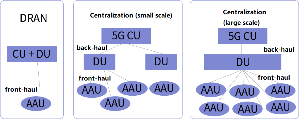
Figure 3-2 5G fronthaul deployment scenario
3.2 DRAN
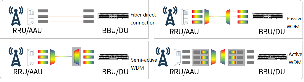
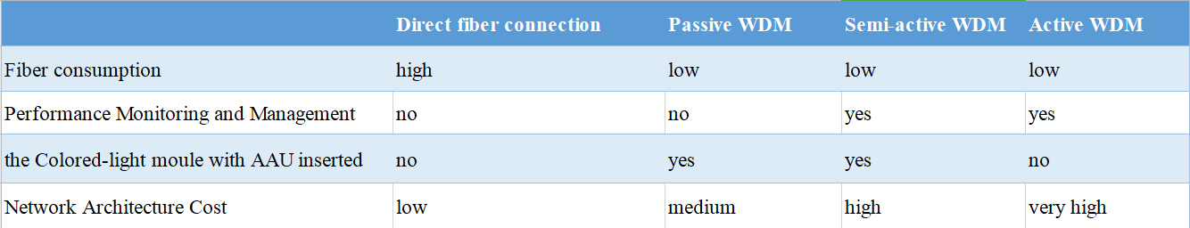
This is a simple scenario where the AAU and DU are deployed at a distance of 300 km or less above and below the tower, respectively. In the CRAN scheme, the maximum distance between the two units is 10km. Both DRAN and CRAN use direct fiber connections for cost-effectiveness and maintenance reasons. In this case, a 25G gray-light module is required.
Figure 3-3 Four different front-haul methods
3.3 CRAN
In the CRAN scenario, a direct fiber connection requires many fibers and cables. In the case of insufficient fiber resources, the use of 10km BiDi gray-light modules can reduce costs because they require half the number of fibers. If necessary, the required fiber resources can be further reduced by using passive WDM and semi-active WDM equipment. In this case, a 25G colored-light module is required.
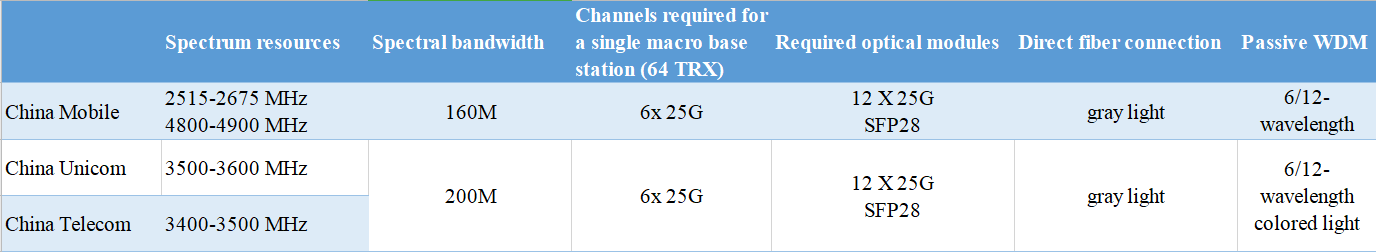
For a single 5G macro base station, one 100MHz spectrum requires three 25Gbit/s eCPRI. In Asia, China Mobile owns 160MHz of 5G spectrum, while China Telecom and China Unicom share 200MHz of 5G spectrum. If the interface rate remains at 25Gbit/s, the number of interfaces will increase from 3 to 6.
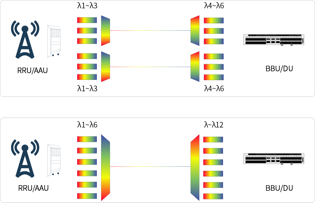
Each macro base station needs six pairs of 25G optical modules to meet the interface transmission requirements. In this case, you can use a set of 12-wavelength colored modules (one fiber per site) or two sets of 6-wavelength colored modules (two fibers per site).
Figure 3-4 Two different approaches to 5G fronthaul passive WDMs
To sum up, both DRAN and CRAN solutions will see a surge in demand for 5G fronthaul optical modules.
4. Different solutions for 25G front-haul
4.1 Background
5G was released in the second half of 2019 and quickly became commercially available in China. By the end of February 2020, 164,000 5G base stations had been deployed. To cope with the rapid and extensive base station construction, operators have chosen colored modules to save costs and achieve rapid commercialization.
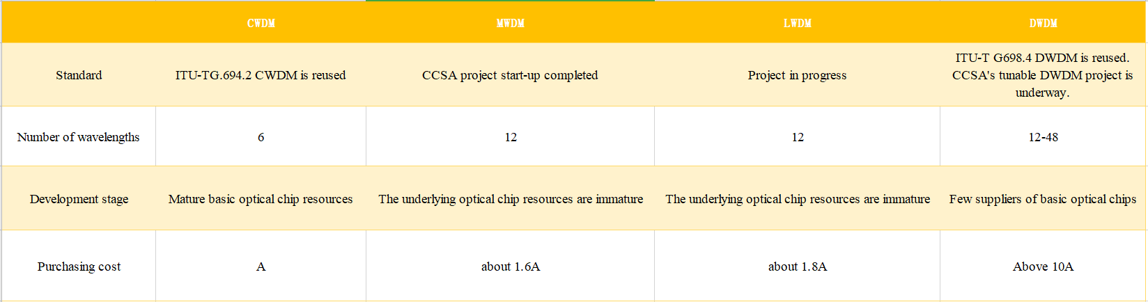
In addition, according to the existing WDM standards, different organizations have proposed CWDM, MWDM, LWDM, and DWDM standards. China Mobile operators also dominate the direct procurement of CWDM optical modules.
4.2 Technology Trends
4.2.1 Reuse existing 10G/25G industry resources
The 25G gray light module utilizes the existing resources in the original 10Gbit/s technology:
-300m SR module uses 850nm vertical-cavity surface-emitting laser (VCSEL);
- -10km LR module uses 1310nm distributed feedback (DFB) laser;
- -The 10 km BiDi module uses a DFB laser (1330 nm upstream, 1270 nm downstream).
- Commercial chips with these wavelengths are readily available. Some chip suppliers can also offer industrial chips suitable for wireless fronthaul applications.
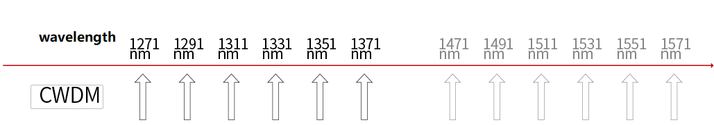
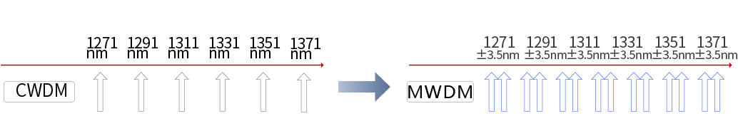
Based on the principle of reusing the WDM standard, the industry is discussing various solutions for 25G color-light modules. The CWDM standard is defined in ITU-T G.694.2. There are 18 CWDM modules with wavelength spacing of 20nm mounted directly on the DU and AAU and using an external CWDM multiplexer/demultiplexer. In a wireless fronthaul scenario with three channels, six wavelengths are required, preferably CWDM 6 waves (1271, 1291, 1311, 1331, 1351, and 1371 nm).
Since the first four wavelengths are the same as that of the CWDM 4-wave DML in the data center, chip vendors only need to develop for industrial temperatures and the last two wavelengths. For six channels, 12 wavelengths are required. Two CWDM 6 waves and two fibers can be selected for transmission, or CWDM 12 waves and one fiber can be selected by adding the last six wavelengths 1471/1491/1511/1531/1551/1571.
Figure 4-1 wavelength of the CWDM
MWDM is a CCSA standard proposed at the end of 2019. In MWDM, each standard wavelength of the CWDM 6 waves is extended by a thermoelectric cooler (TEC) to obtain 12 wavelengths that are not equally spaced.
Figure 4-2 wavelengths of the MWDM
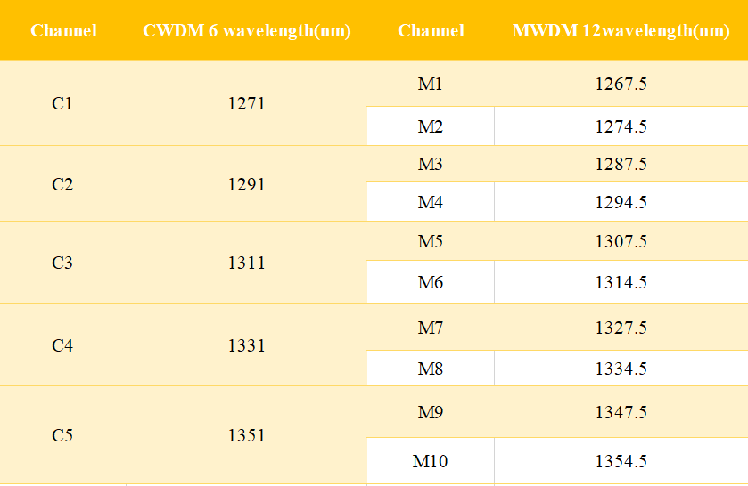
Compared to the CWDM 6-wave, the MWDM 12-wave solution requires the addition of TEC to the optical assembly and the addition of TEC drivers to the module circuit.
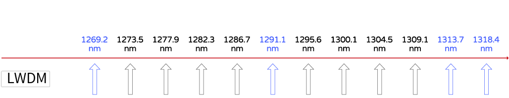
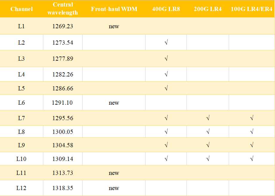
The channel spacing of LAN-WDM technology is 800GHz (about 4.4nm). More wavelengths can be obtained in the O-band with little dispersion loss. IEEE 802.3 defines the 400GE LR8 interface based on LAN-WDM. The last four wavelengths are for 100G LR4, therefore, the industry can easily support the last four wavelengths. If extended to 12 wavelengths, CCSA will add four wavelengths to the 8 LAN-WDM wavelengths to form the LWDM 12 waves. The only difference between LWDM12 waves and MWDM is the optical chip.
Figure 4-3 wavelengths of the LWDM
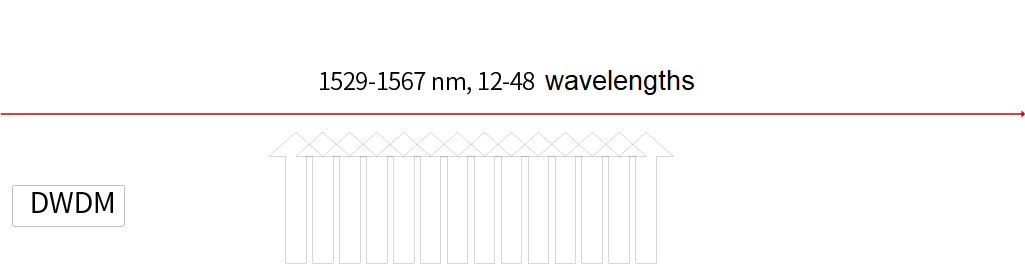
DWDM technology based on ITU-T G.698.4 is widely used in backbone networks and metropolitan area networks. The wavelength range is 1529nm to 1567nm with a spacing of about 0.78 nm. The number of wavelengths can be 6, 12, 20, 40, 48, or 96. However, DWDM modules are expensive and usually deployed in areas with insufficient fiber resources.
Due to the narrow wavelength spacing, MWDM requires TEC controllers and custom wavelength chips. The industry chain of directly modulated laser (DML) optical chips underlying LWDM is not yet mature, the cost of electro-absorption modulated laser (EML) is high, and LWDM requires a TEC controller. DWDM requires a TEC controller, and the chip is expensive. Only CWDM 6 waves do not require TEC controllers and have abundant DML resources, so CWDM 6 is recognized as the most cost-effective solution for operators.
4.2.2 Longer transmission distance
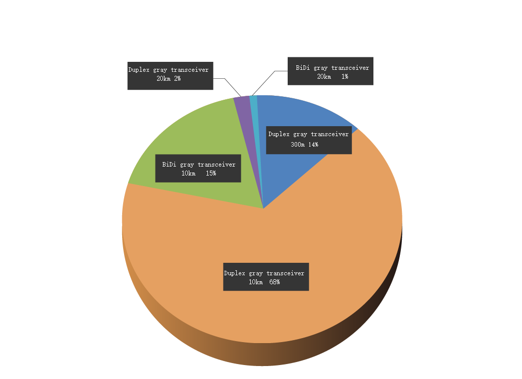
The transmission distance of standard wireless fronthaul optical modules is limited to 10km. With the widespread adoption of CRAN deployments, longer transmission distances may be required on converged fronthaul networks. According to LightCounting, in the next 5 years, 3% of all gray-light modules will require transmission distances longer than 10km. However, industry suppliers are still focusing on 10km optical modules.
The proportion of different types of gray-light modules
4.2.3 Forms of high-density optical modules
Fronthaul communication capacity will need to be gradually increased as 5G develops. However, for wireless base stations, the panel port of the baseband board is fixed. Wireless equipment vendors need to find ways to improve the port's receiving and transmitting capabilities.
Dual Small Form-Factor Pluggable (DSFP) optical modules are a good solution. The DSFP standard released in 2018 supports a maximum rate of 100Gbit/s and is mainly used for Ethernet protocols. It is also suitable for wireless eCPRI fronthaul scenarios. DSFP modules are structurally compatible with SFP modules. Through the integrated package inside the DSFP module, two signal channels can be transmitted, thus doubling the transmission and reception capacity. Currently, 25G SFP modules are standard. However, with the growing demand for fronthaul bandwidth and the development of baseband chips on the BBU side, more DSFP modules may be required.
4.2.4 Adjustable Color-Light Technology
CRAN plays a larger role in the deployment of 5G infrastructure. By 2020, China's three major operators predict that CRAN will account for 80% of 5G infrastructure, so the demand for color-light modules will increase. CWDM 6-wave modules have been widely deployed because they are inexpensive and easy to use. However, wavelength configuration requires a lot of time and effort during the construction and maintenance of base stations. Therefore, a tunable DWDM color-light technology is proposed.
Tunable DWDM systems have the same wavelength range and spacing as fixed DWDM systems. The only difference is that the wavelength-tunable DWDM module supports automatic configuration of 12 or 48 wavelengths. Currently, the tunable DWDM standard is launched in CCSA and the ITU-T G.698.x standard is under revision. Before, DWDM tunable technology has been applied to the transmission networks, but it is much more expensive than the CWDM6 wave. Therefore, the industry has been working hard to reduce the cost of this solution.
5. Wireless Fronthaul 25G Optical Solutions
25G color-light modules can be divided into 25G CWDM 6-wave and adjustable 25G DWDM modules. Customers can choose from different options depending on their needs and budget. The full range of fronthaul 25G optical modules covers various DRAN and CRAN application scenarios.
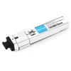
5.1 Different types of 25G gray-light and CWDM 6-wave optical modules
There are several types of 25G gray-light and CWDM 6-wave optical modules:
-25G 300m: dual-fiber bidirectional interface
-25G 10km: dual-fiber bidirectional interface
-25G 10km BiDi: single-fiber bidirectional interface
-25G 10km CWDM6-wave: dual-fiber bidirectional interface; six modules per set
All the optical modules with central wavelengths of 1271/1291/1311/1331/1351/1371nm conform to SFP28 protocols of SFF-8419 and SFF8472.
Electrical ports comply with CEI-28G-VSR. The 25G 10km duplex fiber and 25G 10km BiDi optical ports comply with IEEE 802.3CC 25GBase-LR.
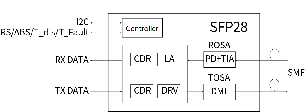
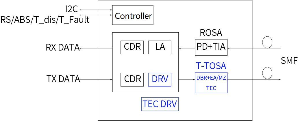
Here is the functional block diagram below, including DML TOSA, PIN ROSA, transmitting CDR, laser driver, receiving LA, receiving CDR, and controller.
Figure 5-1 25G 300m, 10km, and CWDM 6-wave optical modules
Figure 5-2 25G 10km BiDi optical module
In the transmitting direction, the CDR performs clock recovery on the electrical signal received at the edge connector, and the DRV amplifies the signal. Then, the DRV drives the DML TOSA to convert the electrical signal into an optical signal for output.
In the receiving direction, the optical signal is converted into an electrical signal by the PIN PD, amplified by the TIA, and then sent to the LA. After the CDR performs clock recovery, the edge connector performs signal output. CWDM 6-wave uses an uncooled DFB laser. Compared with other WDM solutions, it is more cost-effective and with lower power consumption. This is the ideal solution when a large number of wavelengths are not required.
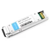
5.2 Tunable 25G DWDM and DWDM 12-wave Optical Module
There are two types of 25G DWDM optical modules:
-48 wavelengths in C-band are tunable and support 10km transmission
-Cost-effective C-band 12-wavelength is tunable and supports 10km transmission. Both conform to SFF-8419 and SFF-8472 protocols. Electrical ports comply with CEI-28G-VSR.
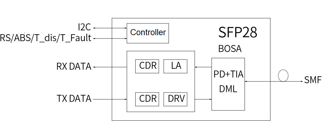
Below is the functional block diagram including T-TOSA, PIN ROSA, transmitting CDR, laser driver, receiving LA, receiving CDR, and controller.
Figure 5-3 25G DWDM optical module
In the transmitting direction, the CDR performs clock recovery on the electrical signal received at the edge connector, and the DRV amplifies the signal. Then, the DRV drives the TTOSA to convert the electrical signal into an optical signal for output.
In the receiving direction, the optical signal is converted into an electrical signal by the PIN PD, amplified by the TIA, and then sent to the LA. After the CDR performs clock recovery, the edge connector performs signal output.
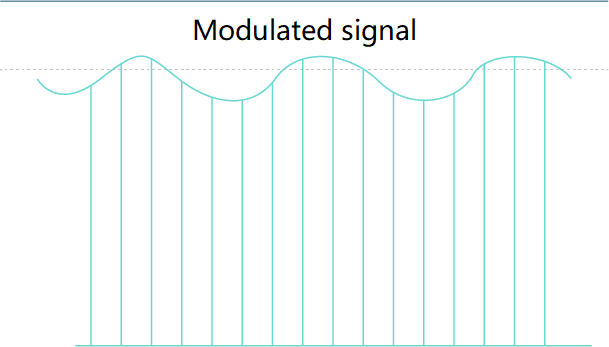
Figure 5-4 Modulated Signal
Conclusion
The eCPRI standard expounds on the 5G fronthaul interface. The 25G fronthaul interface conforms to the Ethernet protocol and provides rich operation and maintenance methods. In addition, existing resources of 25G Ethernet optical modules can be reused. The 25G fronthaul interface has become an industry standard. As capital expenditures for 5G base station construction increase, operators are looking for more cost-effective 25G fronthaul optical modules. Meanwhile, limited optical fiber resources drive the demand for color-light modules. After decades of investment and innovation in the field of optoelectronics, Fiber Mall has launched a complete solution of 25G conventional and WDM optical modules to build the diversification of 5G wireless communication.


 SFP28 C02 1273.54nm 40km LC SMF DDM Transceiver Module")
