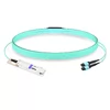
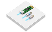
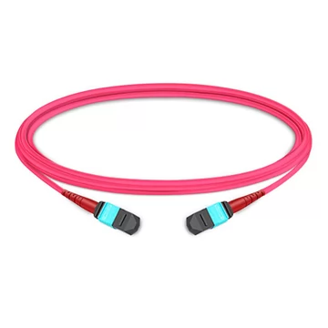
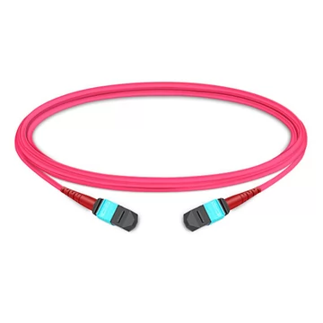
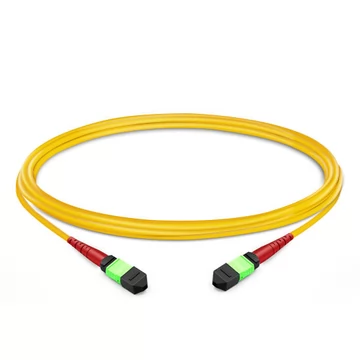
You are pre-cabling a data hall—running the backbone that carries every 40G, 100G, and 400G parallel-optics link from the MDA to the HDA. You order trunks for a hundred racks, and three days before cutover you discover the polarity is inverted, the fiber count does not match the switch ports, or connector insertion loss exhausts the channel budget. By then the raised floor tiles are down, and rework is measured in days of downtime rather than dollars.
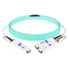
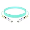
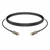
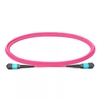
An MTP trunk cable is the highest-leverage component of a high-density structured cabling plant: a single 12- or 24-fiber assembly replaces up to 24 individual duplex patch cords, while a single polarity error propagates across every parallel lane running through it. FiberMall supplies factory pre-terminated MTP/MPO trunk cables built to your exact specifications—fiber count, polarity method, glass type, jacket flame rating, and insertion-loss tier—delivered with per-channel factory test documentation in the box.
The Four Decisions That Make or Break an MTP Trunk Cable Order
Most trunk cable deployment failures stem from ordering errors rather than manufacturing defects. Because a pre-terminated trunk is a custom factory assembly, you cannot field-modify polarity or core counts once the cable is pulled through overhead trays or subfloor pathways. Getting these four parameters right guarantees a seamless commissioning process:
1. Polarity (Type A, B, or C): The primary source of installation failure in structured multi-fiber links. Polarity dictates whether a transmitter channel at one end maps directly to the corresponding receiver channel at the other. Because internal fiber routing is permanently set inside the sealed connector body, a Type A trunk cannot substitute for a Type B trunk; mixing them in a structured channel silently disrupts continuity.
2. Fiber Count (12F vs. 24F vs. Base-8/16): 12-fiber trunks represent the mature, legacy baseline for 40GBASE-SR4 and 100GBASE-SR4 connections. 24-fiber assemblies double pathway density for hyperscale footprints and multi-lane 400G backbones, but require strict management of multi-row pin mapping (top row vs. bottom row) alongside end-to-end polarity.
3. Insertion-Loss Tier (Standard vs. MTP Elite): Standard MTP connectors exhibit a typical insertion loss around 0.60 dB (with maximums up to 0.75 dB), whereas low-loss MTP Elite connectors achieve 0.35 dB maximum. On a single short jumper, the difference is negligible; across a multi-hop cross-connect running 100G or 400G PAM4 optics with tight 1.5–1.9 dB channel budgets, Elite connectors prevent link degradation and packet drops.
4. Connector Gender (Pinned vs. Pinless): Multi-fiber push-on connections rely on stainless steel guide pins in one connector mating with alignment pinholes in the other. Trunk cables are conventionally ordered pinless (female) at both ends, allowing them to mate with pinned (male) transceivers or pinned rear cassette ports. Mating two female connectors results in severe core misalignment and massive optical attenuation, while forcing two male connectors together damages the guide pins and ferrule end-faces permanently.
MTP Trunk Cable Specifications
Below is an overview of the core mechanical, optical, and physical specifications available for pre-terminated trunk assemblies:
· Fiber Count: 8, 12, 16, 24, 48, 72, 96, or 144 fibers (higher sub-unit counts available on request).
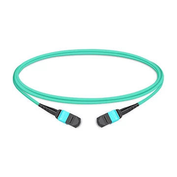
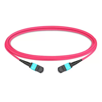
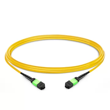
· Fiber Type: Single-mode OS2 (G.657.A1/A2 bend-insensitive); Multimode OM3, OM4, or OM5 (wideband multimode fiber).
· Polarity Methods: Type A (Key-Up to Key-Down, straight 1-to-1 mapping); Type B (Key-Up to Key-Up, full reversal); Type C (Key-Up to Key-Down, pair-flipped).
· Connector Platform: US Conec MTP or compliant MPO connectors; available in female (pinless) or male (pinned) configurations.
· Insertion-Loss Tier: Standard Loss (≤0.60 dB typical, ≤0.75 dB max) or MTP Elite Ultra-Low Loss (≤0.35 dB max).
· Jacket Flame Rating: Low Smoke Zero Halogen (LSZH), Plenum (OFNP), Riser (OFNR), or general-purpose PVC.
· Length: Custom-built to exact run specifications, measured end-to-end in meter or centimeter increments.
· Mechanical Options: Staggered breakout legs, protective pulling eyes with pulling socks, custom channel serialization, and OEM/private-label print streams.
Key production advantages include:
· Pre-terminated and 100% Factory-Tested: Every assembly is verified through interferometry and optical testing, shipping with individualized per-channel insertion loss (IL), return loss (RL), and polarity verification reports.
· MTP Elite Low-Loss Tiers: Low-loss ferrules (≤0.35 dB) provide adequate optical headroom for multi-tier 100G, 400G, and 800G networks.
· Precision Engineered Lengths: Trunks are constructed precisely to engineering drawings, eliminating excess slack storage within congested cable management pathways.
· Industry-Standard Hardware: Terminated with authentic US Conec MTP or standardized MPO connectors, ensuring mechanical and optical interoperability with enterprise transceivers and modular patch panels.
MTP vs. MPO: The Real Engineering Differences
The terms MPO and MTP are often used interchangeably in network design documentation, but they refer to different levels of mechanical tolerance:
MPO (Multi-Fiber Push-On) is the generic international interface standardized under IEC 61754-7 and TIA/EIA-604-5 (FOCIS 5).
MTP is a registered brand name and proprietary design engineered by US Conec. It is a high-precision, enhanced iteration of the generic MPO connector. While fully intermateable with standard MPO interfaces, MTP incorporates distinct mechanical upgrades:
· A floating ferrule design that preserves physical core contact across mated pairs under mechanical cable pull or side-load stress.
· Elliptical, precision-polished stainless steel guide pins that minimize ferrule guide-hole wear and debris generation compared to conventional cylindrical pins.
· Internal metal pin clamps with centering springs that equalize force across all fiber cores, reducing guide-pin shear during mating cycles.
For cost-sensitive applications with loose optical budgets, generic MPO connectors interoperate effectively. For high-speed spines, parallel-optic PAM4 deployments, or links traversing multiple cross-connect cassettes, specifying MTP Elite ensures the lowest total insertion loss and consistent return loss across the entire ferrule.
Polarity: Type A vs. Type B vs. Type C
Optical polarity ensures that optical transmitters (TX) reliably terminate into optical receivers (RX) on opposite ends of a link. The TIA-568 standard outlines three distinct polarity methods for multi-fiber arrays, each requiring matched trunk cables, adapters, and patch cords:
· Type A (Straight-Through): Uses a Key-Up to Key-Down adapter configuration. The internal fiber mapping is direct: Fiber 1 connects to Position 1, and Fiber 12 connects to Position 12. Because it preserves channel indexing end-to-end, correcting for TX-to-RX crossover requires an A-to-B duplex patch cord or a specialized cassette at one end of the link. It is widely applied in classic structured channel distributions.
· Type B (Reversed / Inverted): Employs a Key-Up to Key-Up adapter configuration. The internal fiber routing is completely inverted: Fiber 1 routes to Position 12, Fiber 2 to Position 11, and so forth. This inversion automatically manages the TX/RX crossover at the connector face, making Type B trunks the standard for direct transceiver-to-transceiver parallel optics, such as 40GBASE-SR4, 100GBASE-SR4, and 400GBASE-DR4.
· Type C (Pair-Flipped): Uses Key-Up to Key-Down adapters with adjacent fiber pairs transposed internally: Fiber 1 routes to Position 2, Fiber 2 to Position 1, Fiber 3 to Position 4, and Fiber 4 to Position 3. Designed primarily to manage crossover in duplex communications via MPO-to-LC cassettes, Type C is a legacy format and cannot support modern parallel-optics transceivers.
Maintaining proper polarity requires adhering strictly to a single method end-to-end. For duplex circuits broken out via cassettes, a complete link typically requires an odd number of logical flips across the path. For parallel optics, Type B trunks provide native cross-connection. The three polarity methodologies rely on incompatible adapter keys and internal ribbon mapping; mixing a Type B trunk into a Type A structured link disrupts physical connectivity and stops all traffic across the trunk.
12-Fiber vs. 24-Fiber MTP Trunk Cables
Selecting between 12-fiber and 24-fiber form factors dictates both pathway fill capacity and link migration architecture:
· 12-Fiber MTP Trunks: The standard architecture for Base-12 structured cabling. In 40GBASE-SR4 and 100GBASE-SR4 links, a 12-fiber connector uses the outer 8 fibers (4 transmit lanes, 4 receive lanes) while leaving the central 4 fibers dark. Base-12 components are supported by every major equipment vendor, make polarity management straightforward, and present the lowest implementation risk for greenfield enterprise campuses.
· 24-Fiber MTP Trunks: Feature two rows of 12 fibers within a single standard-footprint ferrule, doubling density per pathway. A single 24-fiber trunk can service two independent 40G/100G links or deliver connectivity to high-lane interfaces like legacy 100GBASE-SR10 or 400GBASE-SR8 (which utilizes 16 active fibers across the array). However, dual-row ferrules require strict attention to upper-row and lower-row channel assignments to avoid TX/RX orientation mismatches.
When comparing the two formats directly:
· Density per Cable Assembly: 12-Fiber MTP carries a single row of 12 cores; 24-Fiber MTP packs two parallel rows of 12 cores into a single ferrule.
· Primary Optical Applications: 12-fiber excels in 40GBASE-SR4, 100GBASE-SR4, and multi-core duplex breakouts. 24-fiber serves high-density spine-leaf backbones, hyperscale data halls, and native high-lane aggregation.
· Polarity Management Profile: 12-fiber uses standard single-row TIA-568 Methods A, B, or C. 24-fiber requires managing both lateral lane mapping and row-to-row (top vs. bottom) lane orientation.
· Deployment Maturity: 12-fiber represents the universal, field-proven standard across enterprise environments; 24-fiber represents a space-optimized footprint tailored for high-density hyperscale facilities.
For modern 400G infrastructure, choose cable architecture based on the specific optical transceiver: 400GBASE-DR4 requires an 8-fiber Base-8 single-mode array (often carried over standard 8F or 12F trunks), while 400GBASE-SR8 requires an MPO-16 single-row or an MPO-24 dual-row connector.
MTP Elite vs. Standard: When Low Loss Matters
Total channel insertion loss encompasses the light attenuated across connector end-faces, bulk fiber propagation, and fusion splices. In high-speed links, excessive insertion loss quickly compromises link margins:
· Standard MTP: Typically exhibits insertion loss of ~0.60 dB (with maximums up to 0.75 dB). This performance is suitable for short runs, single-hop architectures, or links operating with generous optical power margins.
· MTP Elite: Precision-machined ferrules and optimized fiber geometry limit insertion loss to ≤0.35 dB maximum. These connectors are engineered for high-performance networks with minimal optical tolerances.
Optical insertion loss budgets tighten as lane modulation and speeds advance. For example, while 10G Ethernet permitted a generous channel budget of 2.6 dB, 400GBASE-SR8 and 100GBASE-SR4 reduce available connector allocation to under 1.5–1.9 dB. In a channel that routes through patch panels, distribution cassettes, and cross-connects, two standard MTP mated pairs can consume 1.2–1.5 dB on their own, leaving zero margin for patch cord wear or macrobends. Under tight loss budgets, specifying MTP Elite is essential to avoid bit errors and intermittent interface resets.
Applications: Where MTP Trunk Cables Carry the Load
MTP trunk cables serve as the primary structured cabling medium across mission-critical facilities:
· 40G and 100G Server Aggregation: 12-fiber trunks linking Main Distribution Areas (MDA) to Horizontal Distribution Areas (HDA) and Top-of-Rack (ToR) switches running QSFP+/QSFP28 transceivers.
· 400G and 800G Spine-Leaf Fabrics: High-fiber-count single-mode (DR4/XDR4) and multimode (SR8) MTP backbones linking spine switches to distribution fabrics with minimal cable tray bulk.
· Hyperscale Cloud Facilities: High-density 24-fiber and multi-subunit trunking designed to maximize pathway airflow and reduce underfloor pathway congestion.
· Modular Pre-Terminated Distribution: Factory-assembled trunks deployed alongside high-density breakout cassettes to eliminate the labor, time, and variable optical quality of field fusion splicing.
· Central Offices and Optical Distribution Frames (ODF): High-core OS2 single-mode MTP backbones providing clean, high-density interconnection across telecommunications aggregation racks.
MTP Trunk Cable FAQ
What is an MTP trunk cable?
An MTP trunk cable is a factory pre-terminated, multi-fiber optical cable assembly—typically built with 8, 12, 16, or 24 fibers per connector—fitted with high-density MTP/MPO interfaces at both ends. It serves as the primary backbone in data centers, routing tens or hundreds of fibers through a single compact outer jacket.
What is the difference between MTP and MPO?
MPO is the open industry standard (IEC 61754-7) for push-on multi-fiber connectors. MTP is a high-precision, branded connector manufactured by US Conec. MTP connectors are fully backward-compatible with MPO receptacles, but offer structural enhancements such as floating ferrules, low-wear elliptical alignment pins, and balanced spring mechanisms to minimize insertion loss and wear.
Which polarity method should I choose: Type A, B, or C?
Your selection depends on your channel architecture and optical transceivers. Type B (Key-Up to Key-Up) is standard for parallel optics like 40G/100G/400G QSFP links because it inherently crosses transmit channels to receive channels. Type A (Key-Up to Key-Down) is common in structured breakout channels utilizing modular patch cassettes. Type C is a legacy pair-flipped standard used primarily in older duplex installations. Maintain the same polarity methodology across trunks, adapters, and patch cords throughout the entire link.
Should I deploy 12-fiber or 24-fiber MTP trunk cables?
Choose 12-fiber (or Base-8 variants) for mainstream enterprise deployments, standard 40G/100G SR4 optics, and simpler polarity tracking. Choose 24-fiber when optimizing pathway fill, maximizing rack-to-rack density in hyperscale environments, or directly provisioning multi-lane high-speed interfaces like 400GBASE-SR8.
When is MTP Elite insertion loss necessary?
Standard connectors typically introduce 0.60 dB of loss, whereas MTP Elite connectors guarantee ≤0.35 dB. MTP Elite is recommended whenever you are deploying 100G, 400G, or 800G optics with strict optical link budgets, or whenever a structured channel passes through two or more cassette interfaces before reaching its endpoint.
Can trunk cables be customized by length and fiber configuration?
Yes. Factory-built MTP trunk cables can be manufactured to exact lengths in meter or centimeter increments, configured with custom fiber types (OS2, OM3, OM4, OM5), built to specific polarity configurations, jacked in plenum (OFNP) or LSZH compounds, and packaged with heavy-duty pulling eyes for safe pathway routing.